WIKA SL-1 User Manual
Page 6
2488791.07 GB/D/F 06/2010
10 WIKA Operating instructions/Betriebsanleitung/Mode d'emploi SL-1
2488791.07 GB/D/F 06/2010
11
WIKA Operating instructions/Betriebsanleitung/Mode d'emploi SL-1
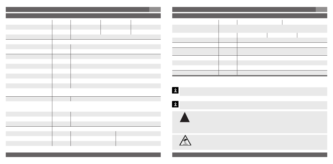
Specifications
Model SL-1
Pressure ranges
mbar
25
40
60
Over pressure safety
mbar
500
500
500
Pressure ranges
mbar
1000
1000
1000
Type of Pressure
Relative pressure
Materials
Wetted parts
Stainless steel, silicon, aluminium, gold, silicone
Case
Stainless steel
Power supply U
B
DC 10
... 30 V (DC 14 … 30 V with signal output 0 … 10 V)
Signal output and
R
A
in Ohm
4 … 20 mA, 2-wire
R
A
≤ (U
B
– 10 V) / 0.02 A
maximum ohmic load R
A
{0 … 5 V, 3-wire}
R
A
> 5000
{0 … 10 V, 3-wire}
R
A
> 10000
{other signal output on request}
Adjustability zero/span
%
±
5 using potentiometers inside the instrument
Insulation voltage
DC 500 V *
)
*
)
Use NEC Class 02 power supply (low voltage and low current max. 100 VA even
under fault conditions)
Accuracy **
)
% of span
≤
0.5
**
)
Including non-linearity, hysteresis, zero point and full scale error (corresponds to
error of measurement per IEC 61298-2).
Adjusted in vertical mounting position with lower pressure connection.
Non-linearity
% of span
≤
0.2
(BFSL) according to IEC 61298-2
Non-repeatability
% of span
≤
0.1
1-year stability
% of span
≤
0.3
(at reference conditions)
Permissible temperature of
Medium
-30 ... +80 °C
-22 ... +176 °F
Ambience
-20 ... +80 °C
-4 ... +176 °F
Storage
-40 ... +80 °C
-40 ... +176 °F
Specifications
Model SL-1
Rated temperature range
0 ... +80 °C
32 ... +176 °F
Temperature coefficients within
rated temperature range
Mean TC of zero
% of span
25 mbar: 0.5 / 10 K
40 mbar: 0.4 / 10 K
60 mbar: 0.3 / 10 K
Mean TC of range
% of span
≤
0.3 / 10 K
RoHS-conformity
Yes
CE-conformitiy
2004/108/EC, EN 61 326 Emission (Group 1, Class B) and Immunity
(industrial locations)
Wiring protection
Short-circuit proofness
Sig+ towards 0V/Sig-
Reverse polarity protection
UB+ towards 0V/Sig-
Weight
kg
Approx. 0.3
7. Starting, operation
GB
7. Starting, operation
GB
{ } Items in curved brackets are optional extras for additional price.
Functional test
Open pressure connections only after the system is without pressure!
Observe the ambient and working conditions outlined in section 7 „Technical
data".
Please make sure that the pressure transmitter is only used within the over-
load threshold limit at all times!
When touching the pressure transmitter, keep in mind that the surfaces of
the instrument components might get hot during operation.
When designing your plant, take into account that the stated values (e.g.burst pressure,
over pressure safety) apply depending on the material, thread and sealing element used.
The output signal must be proportional to the pressure. If not, this might point to a
damage of the diaphragm. In that case refer to chapter 10 „Troubleshooting“.
Warning
Caution
!