WIKA SL-1 User Manual
Page 5
2488791.07 GB/D/F 06/2010
8 WIKA Operating instructions/Betriebsanleitung/Mode d'emploi SL-1
2488791.07 GB/D/F 06/2010
9
WIKA Operating instructions/Betriebsanleitung/Mode d'emploi SL-1
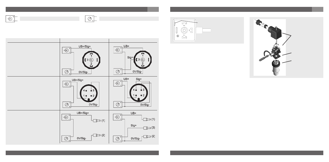
7. Starting, operation
GB
Load (e.g. display)
Power supply
UB+/Sig+
Positive supply / measurement connection
OV/Sig-
Negative supply / measurement connection
Circular connector
M 12x1,
IP 67
Flying leads with 1.5 m of cable,
conducter cross section up
to max. 0.5 mm ², AWG 20
with end splices, conducter outer
diameter 6.8 mm;
cable screen: grey
IP 67
L-Connector,
DIN EN 175301-803, Form A
for conducter cross section up
to max. 1.5 mm², conducter
outer diameter 6 to 8 mm
IP 65
3-wire
2-wire
brown
green
brown
green
white
(D) Mounting hole
1. Loosen the screw (1).
2. Loosen the cable gland (2).
3. Pull the angle housing (5), with the
terminal block (6) inside, away from the
instrument.
4. Using the head of a small screwdriver in
the mounting hole (D), lever the terminal
block (6) out of the angle housing (5).
In order not to damage the sealing of the angle housing, do not try to push the terminal
block (6) out using the screw hole (1) or the cable gland (2).
5. Ensure that the conductor outer diameter you select is matched to the angle housing’s
cable gland. Slide the cable through the cable gland nut (2), washer (3), gland seal (4) and
angle housing (5).
6. Connect the flying leads to the screw terminals on the terminal block (6) in accordance
with the pin-assignment drawing.
7. Press the terminal block (6) back into the angle housing (5).
8. Tighten the cable gland (2) around the cable. Make sure that the sealing isn’t damaged
and that the cable gland and seals are assembled correctly in order to ensure ingress
protection.
9. Place the flat, square gasket over the connection pins on the top of the instrument
housing.
10. Slide the terminal block (6) onto the connection pins.
11. Secure the angle housing (5) and terminal block (6) to the instrument with the screw (1).
Assembly of L-connector DIN EN 175301-803
(6)
(5)
(1)
(2)
(3)
(4)
Clamping nut,
Male connector,
Case with
pressure connection
Sealing
Female
connector
7. Starting, operation
GB