DuraVent Type B Gas Vent User Manual
Page 7
7
3. Ceiling Support. For a ceiling supported
system, install the Square Firestop/Support as
shown in Figures 6, 7, and 8. The Firestop
Support must be framed in and the dimensions
are shown in Table 1 and shown in Figure 4.
Firestop Supports are currently manufactured
for pipe sizes of 3” through 12” only. Larger
sizes may be locally fabricated from sheet
metal, provided that the mandatory 1-inch
clearance is maintained, the pipe is adequately
supported, and the installation is acceptable
to Local authorities. In multistory buildings,
a Firestop/Spacer must be provided at every
floor /ceiling level other than the first floor
which requires a support.
4. Wall Thimble. For a through-the-wall
system, install the Wall Thimble, as shown in
Figure 5. The Wall Thimble is designed to
accommodate walls up to 6 inches thick. If
you have thicker walls, a sleeve extension
should be fabricated and attached to the
existing sleeve . Do not fill the air space
between the B-vent pipe Section and the Wall
Thimble with insulation, although an RTV-type
sealant may be applied around the flange and
nail heads if desired.
5. Pipe Assembly. Sections of DuraVent
round pipe are joined together by lining up the
female end of the locking lug with the male
end slot, pushing them together, and turning
clockwise to twist lock. Refer to Figure 9.
Sheet metal screws are not needed for 3”
through 8” diameter pipe. However, if desired,
use 1/4-inch long sheet metal screws for 3”
through 8” diameter pipe. never penetrate
the inner liner with screws. For 10” through
16” diameter pipe, DuraVent recommends
using a minimum of (4) 3/8” sheet metal screws
per joint, and a minimum of (6) 3/8” sheet metal
screws are required per joint for 18” and larger
diameters. Each pipe Section is labelled, and
an arrow shows the direction of the exhaust flow.
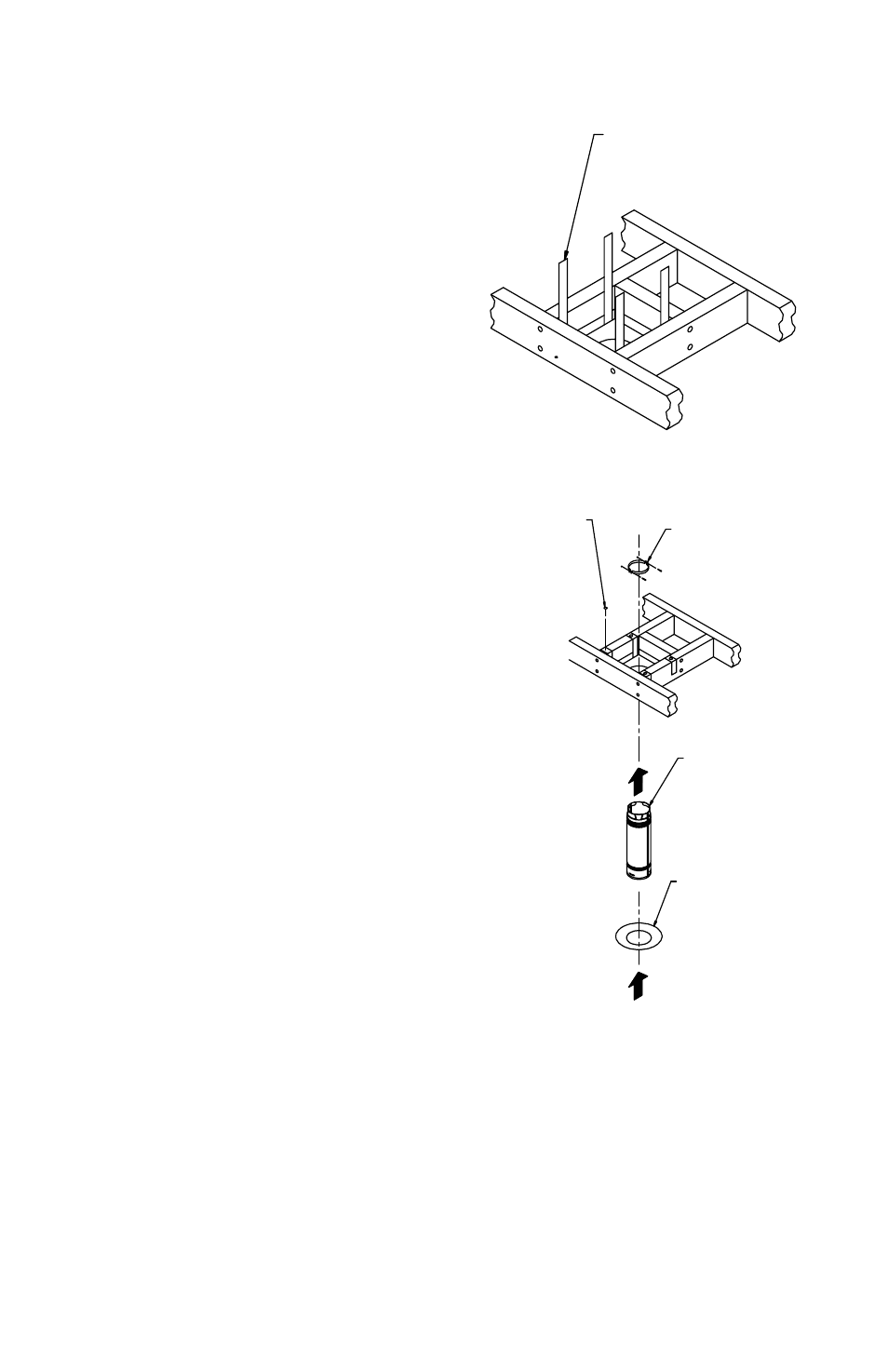
Figure 7
HanGER
STRapS
Figure 8
cLaMp
pIpE cOLLaR
(OpTIOnaL)
B-VEnT pIpE
SEcTIOn
naILS
(4 REQ)
For ceiling supported installations, place a pipe
Section, or assembled pipe Sections, through
the hole in the Square Firestop Support, and
tighten the clamp. The clamp will rest inside the
ceiling Support, and prevent the pipe Sections
from dropping down. The pipe Section(s) should
protrude a minimum of one inch below the ceiling.