DuraVent Type B Gas Vent User Manual
Page 14
14
the appliance manufacturer for clarification.
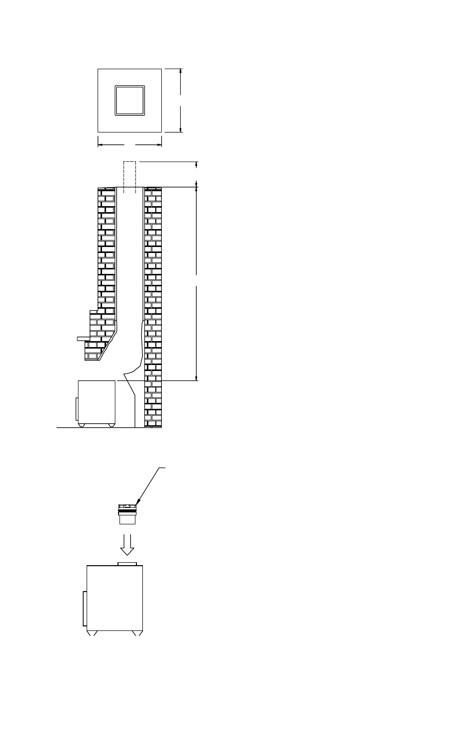
place the appliance out in front of the fireplace
area, as shown in Figure 27, and install the
Draft Hood connector, or other device in
accordance with the appliance instructions.
The Flex pipe coupling may be able to attach
directly to the appliance.
(d). Flex Pipe Assembly. assemble first Rigid
pipe Section to the Flex pipe, insuring that the
“up” arrows are in fact, pointing up. push the
sections together and twist to lock. Screws are
not required, however if you desire to use them,
use #8 sheet metal screws 1/4-inch long, being
careful to not penetrate the inner liner. Repeat
this process for the remainder of the pipe
Sections, and lower the assembly down the
chimney. Lower it below it’s normal position as
shown in Figure 28.
(e). Position and Connect Fireplace. push
the gas fireplace towards the firebox, and
connect the Flex pipe female coupling to the
appliance, or to the appropriate connector as
specified by the appliance manufacturer. If
insufficient space is available between the top
of the appliance, and the fireplace opening,
an access opening in the opposite side of the
masonry chimney may be necessary. position
the gas appliance on it’s final location, again
complying with the manufacturer’s instructions
in regards to location. Install any shields or
covers at this time.
(f). Adjust Height. Go to the top of the chimney
and pull the vent system up to its desired height.
In most cases, this will be 15 inches above
the masonry surface. Make a mark on the
pipe Section even with the top of the masonry
surface. If the top of the pipe is near a steep
roof (more than 7/12 pitch) ,use the height as
stated in Table 2.
(g). Flashing. Bend and trim the base of the
Tall cone Flashing so it fits onto the top of the
masonry chimney. use masonry anchors and
Figure 25
Figure 26
A
B
C
15 IncHES
DRaFT HOOD
cOnnEcTOR