DuraVent Type B Gas Vent User Manual
Page 20
20
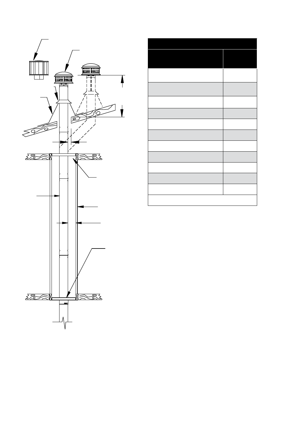
TABLE 1
Roof Pitch
Minimum
Height*
FLaT TO 7/12
1.0
OVER 7/12 TO 8/12
1.5
OVER 8/12 TO 9/12
2.0
OVER 9/12 TO 10/12
2.5
OVER 10/12 TO 11/12
3.25
OVER 11/12 TO 12/12
4.0
OVER 12/12 TO 14/12
5.0
OVER 14/12 TO 16/12
6.0
OVER 16/12 TO 18/12
7.0
OVER 18/12 TO 20/12
7.5
OVER 20/12 TO 21/12
8.0
*THIS REQUIREMENT COVERS MOST INSTALLATION
Gas venting systems using vent caps
listed by underwriters’ may terminate in
accordance with this vent termination table.
Where the vent passes through the roof,
the roof sheathing is cut away to provide a
minimum clearance of 1 inch from the vent
pipe. Straight lengths of pipe are run up about
a foot above the roof. a roof flashing is placed
down over the pipe, and adjusted so the
flashing fits tightly against the roof, with the
vent pipe held in a position maintaining the
1-inch minimum clearance from combustibles.
The flashing is then nailed to the roof. a non-
hardening sealant may be used around the
edges of the flashing base where it meets the
roof. non-hardening sealant is placed around
the joint between the flashing and the vertical
vent pipe, and the storm collar is then placed
over this joint to make a watertight seal. The
storm collar serves as a counter-flashing to
give additional protection.
HIGH WInD cap
D
uRa
c
ap
STORM
cOLLaR
FLaSHInG
pIpE
ROunD pIpE
SEE TaBLE 1
1 IncH MInIMuM
cLEaRancE
FIRESTOp
SpacER
EncLOSuRE
WaLL
1 IncH
MInIMuM
cLEaRancE
GaS VEnT
SuppORT