Adjustable elbows – DuraVent Type B Gas Vent User Manual
Page 11
11
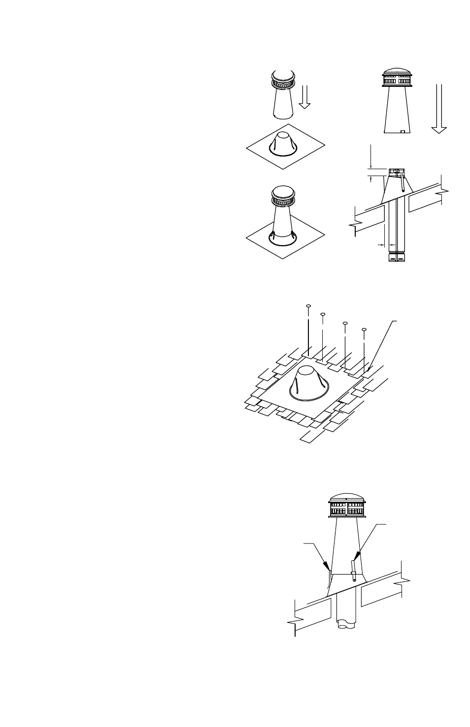
Figure 15
Figure 16
Figure 17
Figure 18
of the roof where the system is to penetrate,
using a plumb bob or level.
3. Hole. Remove sufficient roofing material
to cut a hole in the roof which will allow a
minimum of 1 inch air space between the
B-Vent and combustible roofing materials.
4. Flashing. position the Flashing so the hole
is directly over the end of the pipe, as shown in
Figure 16. Run the top edge of the Flashing
under the roof covering, nail as required, and
seal with a non-hardening sealant, as shown in
Figure 17. Seal all nail heads.
5. Height. add sufficient pipe Sections of
B-Vent until the system terminates 1-1/2” to 3”
above the collar of the Flashing as shown in
Figure 16.
6. Top Cone. Slip the Top cone over the
Flashing, so the vertical straps on the Flashing
coincide with the slots at the base of the
cone. Slip the straps up through the slots as
shown in Figure 18. adjust the Top cone to
a generally vertical position. Holding the Top
cone in position, bend the straps down as
shown.
7. This completes the installation. conduct
a final inspection of the job to ensure proper
joints, correct procedures, sealed nail heads,
etc.
ADJUSTABLE ELBOWS
1. Purpose. This section furnishes
supplemental information concerning
adjustable Elbows, both 90° and 45°/60°.
2. Connections. In addition to twist locking
the elbows, the connection may be further
secured by using sheet metal screws at the
joint where the male and female parts overlap,
provided that the screws DO NOT penetrate
the inner liner as shown in Figure 19. One
screw per joint is normally sufficient. use #8
pan Head sheet metal screws which are no
longer than 1/4 inch. Wall Straps must be
Run TaBS On
FLaSHInG up THRu
RaISED SLOTS On
cOnE
anD THEn
FOLD THEM
OVER TO HOLD
cOnE TO
FLaSHInG
1 1/2 to 3
IncHES
1 IncH
MInIMuM
appLy
WEaTHERpROOF
SEaLanT
BETWEEn
FLaSHInG anD
ROOF On aLL
SIDES anD TO naIL
HEaDS.