DuraVent Type B Gas Vent User Manual
Page 16
16
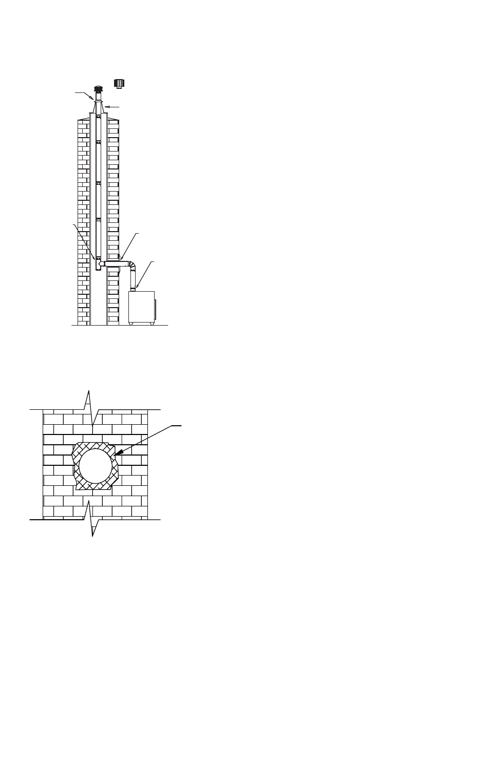
Figure 30
Figure 31
(c). Tee. a Tee is installed at the bottom end
of the assembled vertical pipe Sections, as
shown in Figure 30. The Tee has a removable
Tee cap at the bottom, for cleaning and
condensate removal. If the configuration of the
building permits it, a clean-out access gate is
recommended.
(d). Vertical Pipe Sections. Run the
assembled vertical pipe Sections (with the Tee
attached to the bottom), down the chimney,
until the horizontal branch of the Tee is
opposite the hole in the masonry.
(e). Adjust Height. Hold the assembled pipe
Sections in this position, and make a mark
even with the top surface of the masonry
chimney. The vertical pipe Sections should
protrude 12 inches (in most cases) above this
mark. If the top of the pipe will be near a steep
roof (more than 7/12 pitch), use the height as
stated in Table 2.
(f). Flashing. Bend and trim the base of the
Tall cone Flashing so it fits onto the top of the
masonry chimney. use masonry anchors and
non-hardening sealant to secure the flashing to
the masonry (Figure 28).
(g). Storm Collar. Slide the Storm collar over
the pipe down to top of the Flashing. Secure
the Storm collar in place with at least (3)
1/4” sheet metal screws (Figure 29). Do not
penetrate the inner liner. The Storm collar and
Flashing will support the weight of the vent
assembly. use non-hardening sealant around
the top of Storm collar to make a weatherproof
seal.
(h). Horizontal Pipe Section(s). Run the
horizontal pipe Section(s) through the hole
in the masonry, and connect it firmly to the
Tee, either by reaching through the hole, and
holding the Tee while twisting the pipe Section,
or by holding the Tee through the access door
while someone twist-locks the pipe Section to
it. use an adjustable pipe Length as needed
cERaMIc FIBER
InSuLaTIOn
TEE
TRIM COLLAR
OPTIONAL
HIGH WIND
CAP
FLASHING
STORM COLLAR
WITH SCREWS
DRAFT HOOD
CONNECTOR (IF
REQUIRED)
GAS
APPLIANCE