Steps for typical installation, Figure 1 – DuraVent Type B Gas Vent User Manual
Page 5
5
Figure 2
at least 2 feet higher than an adjacent wall
or obstruction, if it is within 8 feet. Vent pipe
with 14” or larger diameter must terminate
at least 2 feet higher than an adjacent wall or
obstruction, if it is within 10 feet.
8. Connector Rise. plan a minimum of one
foot vertical connector rise coming out of each
appliance.
STEPS FOR TYPICAL
INSTALLATION
1. Location. Building code requires the
appliance(s) to be located as close to the vent
as possible. after consulting the local codes,
appliance installation instructions and any
other applicable reference material determine
the optimum location for the appliance(s).
2. Penetration Point. Locate and mark the
center of the penetration point through the
ceiling or the wall. Refer to Step 3 or 4, as
appropriate.
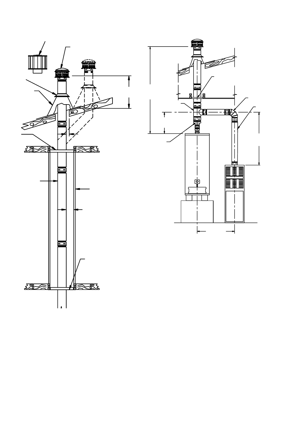
TOTaL
VEnT
HEIGHT
WaTER HEaTER
WITH DRaFT HOOD
LaTERaL
FuRnacE
cOnnEcTOR RISE
cEILInG SuppORT /
FIRESTOp
90° aDJuSTaBLE
ELBOW
IncREaSER
B-VEnT
pIpE
B-VEnT TEE
WaTER HEaTER
cOnnEcTOR RISE
Fan aSSISTED
FuRnacE
Figure 1
FLaSHInG
DuRacap TOp
HIGH WInD cap
SEE TaBLE 2
1 IncH MInIMuM
cLEaRancE
(aLL SIDES)
B-VEnT
1 IncH MInIMuM
cLEaRancE
(aLL SIDES)
FIRESTOp
SpacER
DOTTED LInES
SHOW pOSSIBLE
OFFSET In aTTIc
SpacE
EncLOSuRE
cEILInG SuppORT
/ FIRESTOp
VEnT c OnnEcTS
TO appLIancE
STOR M
cOLLaR