Male and female adapters – DuraVent Type B Gas Vent User Manual
Page 12
12
Figure 19
Figure 20
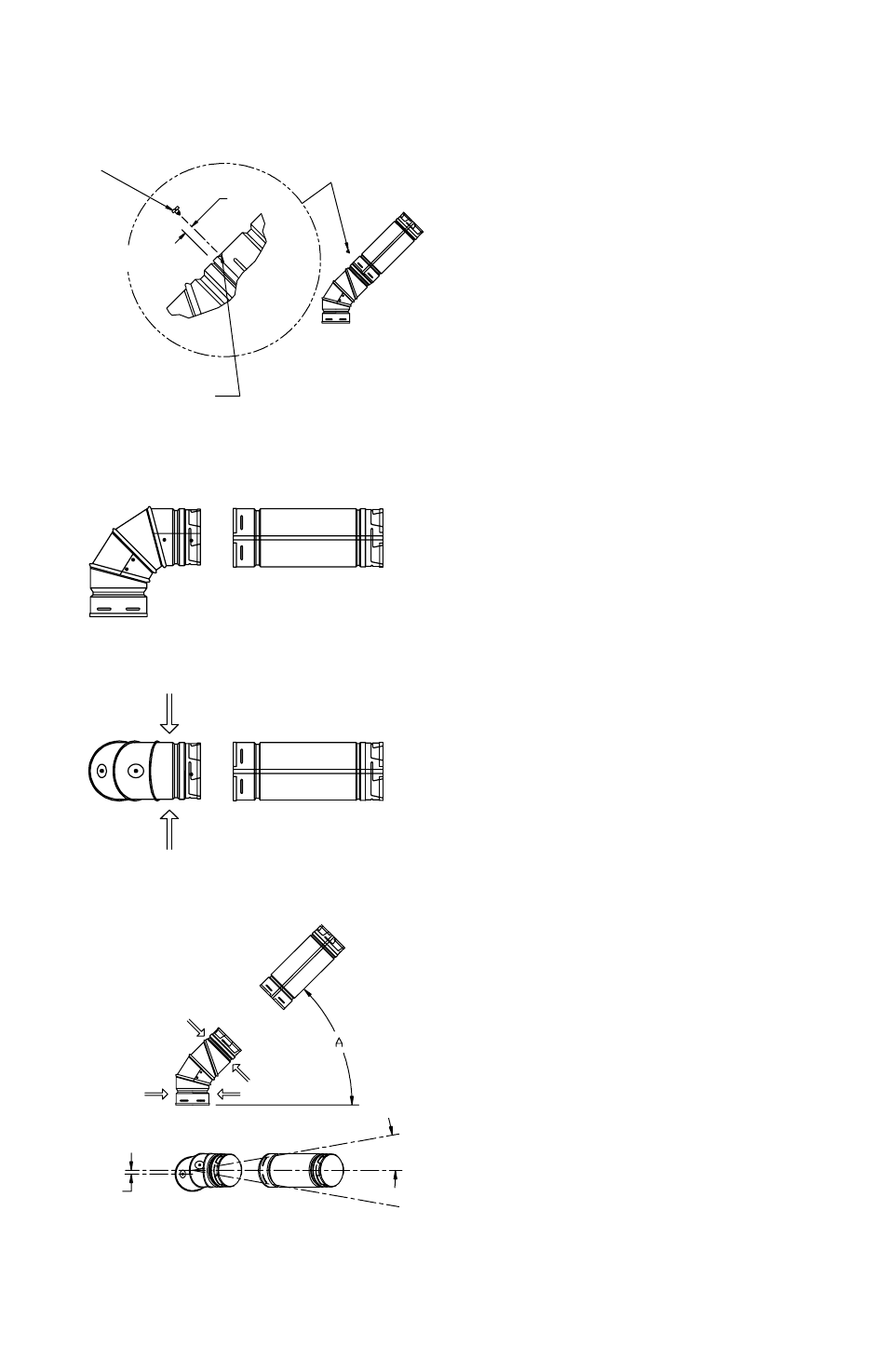
Figure 21
used to support each elbow (Figure 10). Do
not allow the elbows to support the weight of
the vent pipe.
3. 90° Elbows. Figure 20. The installer
should apply pressure to the section at the
points indicated by the arrows. This will
prevent the adjacent sections of the elbow
from turning, as the next pipe or fitting is twist-
locked on. This is important, because once
these sections start rotating, the elbow does
no longer have a 90° angle.
4. 45° Offsets with 90° Elbows. Figure 21
shows a 90° adjustable Elbow being utilized
to accomplish a 45° offset. This Elbow is
completely adjustable from 0° to 90°. please
note that the centers of the upper sections
tend to displace by a slight amount, as they
are rotated. again, screws (not longer than
1/4”) may be used to secure the joint. Wall
Straps should also be utilized to enhance the
stability of the vent system.
MALE AND FEMALE ADAPTERS
1. Description. The male and female
adaptors enable an installer to connect
DuraVent B-vent components to an existing
Type B gas vent system manufactured by
the following companies: american Metals
products, Household Mfg, Hart & cooley Mfg,
Metal Fab, Inc, White Metal products, air Jet,
Mitchell Metal products.
2. Connecting into Existing Competitors
System. To connect into an existing
competitors gas venting system from below,
or from the appliance side, connect a Female
adaptor as shown in Figure 22, insuring
that the inner liner of the adaptor is outside
the inner liner of the existing pipe. push the
adaptor as far up as it will go, and tighten the
locking bolt until the connection is snug.
3. Extending an Existing Competitors
System. To continue an existing competitors
SHEET
METaL
ScREW 1/4
IncH LOnG
DRILL 1/8 IncH DIaMETER
HOLE. DO NOT pEnETRaTE
InnER LInER