2 connecting the pt-110edid xga/line transmitter, Connecting the pt-110edid xga/line transmitter, Figure 9: pt-110edid xga line transmitter – Kramer Electronics TP-125EDID User Manual
Page 25
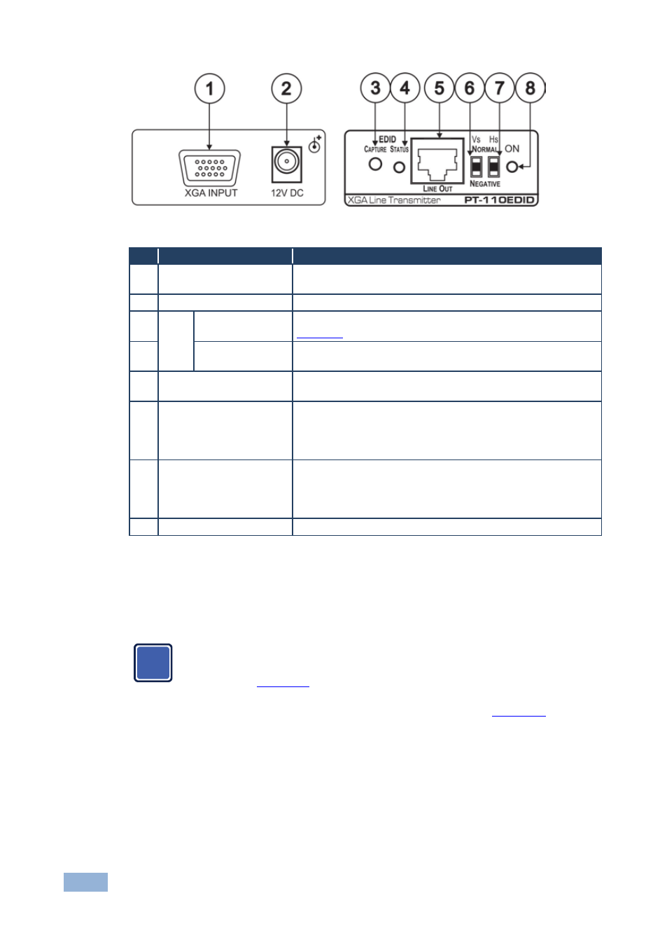
22
TP-121/3/5EDID, PT-110EDID - Your PT-110EDID
Figure 9: PT-110EDID XGA Line Transmitter
#
Feature
Function
1
XGA IN 15-pin HD (F)
Connector
Connect to the UXGA source
2
12V DC
+12V DC connector for powering the unit
3
EDID CAPTURE Button Press to acquire the EDID information from the display (see
4
STATUS LED
Illuminates during normal operation; flashes when acquiring
the EDID
5
LINE OUT RJ-45
Connector
Connects to the LINE IN RJ-45 connector on the TP-120
UXGA/Audio Line Receiver
6
VS Switch
Slide up to set the V SYNC to NEGATIVE polarity;
slide down to set the V SYNC to NORMAL polarity
By default, both switches are set down (for normal V SYNC and
H SYNC polarity)
7
HS Switch
Slide up to set the H SYNC to NEGATIVE polarity (NEG);
slide down to set the H SYNC to NORMAL polarity
By default, both switches are set down (for normal V SYNC and
H SYNC polarity)
8
ON LED
Illuminates when receiving power
7.2
Connecting the PT-110EDID XGA/Line Transmitter
You can use the PT-110EDID XGA Line Transmitter together with the TP-120 XGA
Line Receiver to configure an XGA-to-Twisted Pair transmitter and receiver system.
Before connecting the transmitter and receiver system you can
acquire the EDID from the display or set the system to the default
EDID, see
To connect the PT-110EDID with the TP-120, as the example in
illustrates, do the following:
1. On the PT-110EDID, connect the XGA source (for example, the 15-pin HD
output from a computer’s graphics card) to the XGA INPUT 15-pin HD (F)
connector.
2. On the TP-120, connect the XGA OUT 15-pin HD (F) connector to the XGA
acceptor (for example, a monitor).
i