Figure 2: sl-14rc/n master controller rear panel – Kramer Electronics RC-3TBU User Manual
Page 9
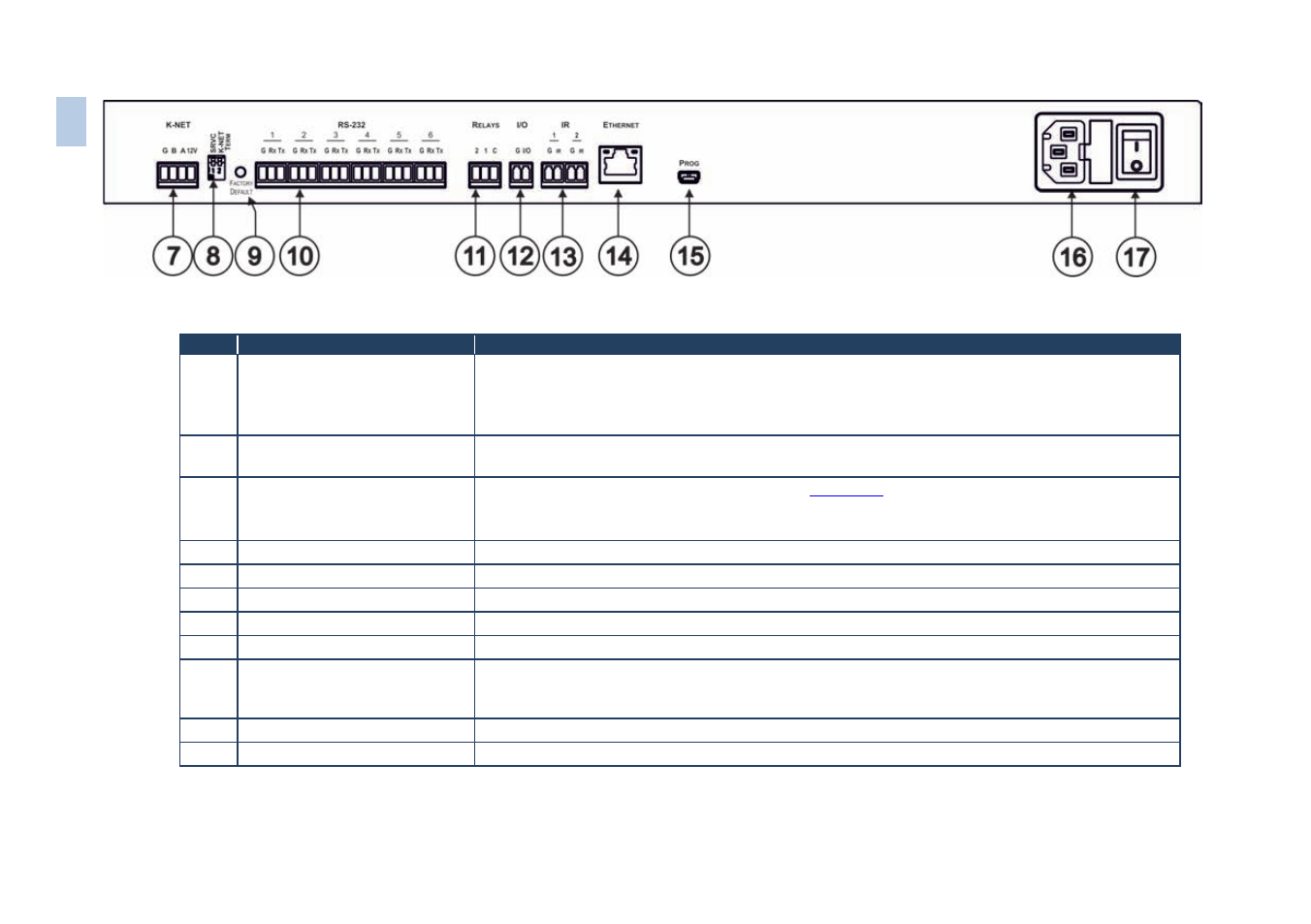
Figure 2: SL-14RC/N Master Controller Rear Panel
#
Feature
Function
7
K-NET Connector
Connect the GND pin to the Ground connection; pin B (-) and pin A (+) are for RS-485, and the
+12V pin is for powering the unit
The ground connection is sometimes connected to the shield of the RS-485 cable (in most applications, it is
not connected)
8
SRVC and K-NET TERM
DIP-Switches
For service use only. Slides down for K-NET termination, slides up for not terminated
9
FACTORY DEFAULT Button
Press to reset to factory default definitions (see
Section 11
First switch off the unit and then switch it on while pressing the DEFAULT button. The unit powers up and
loads its memory with the factory default definitions and erases all stored presets
10
RS-232 Terminal Blocks
Connect to the RS-232 devices (from 1 to 6)
11
RELAYS Terminal Blocks
Connect to low-voltage relay-driven devices (from 1 to 2)
12
I/O Terminal Block
Connect to various analog and digital sensors
13
IR Output Terminal Blocks
Connect to IR emitter cables (from 1 to 2)
14
ETHERNET RJ-45 Connector
Connects to the PC or other serial controller through computer LAN
15
PROGRAM USB Connector
(on the SL-14RCN)
Connects to a PC for software upgrading
On the SL-14RC this USB port is located behind the front panel (remove it by opening the four hex
screws)
16
Power Receptacle
Connects to mains power
17
Power ON/OFF Switch
Illuminated switch for turning the unit on and off
Note: In earlier versions (that is, with the SL-14RC) the USB connector is accessed via the front panel by removing the four front panel screws.
6
SL
-1
4R
C
/N
–
D
e
fin
in
g
t
h
e
S
L
-14
R
C
/N
M
a
st
er
C
o
n
tr
o
ller