Kramer Electronics RC-3TBU User Manual
Page 11
8
SL-14RC/N - Defining the Remote Control Panels
#
Feature
Function
5
8 Position Rotary
Switch
For assigning which buttons on the SL-14RC/N are
emulated by the buttons on the RC-3TB
6
K-NET Termination
Switch
Terminates the K-NET to RC-3TB daisy-chain
7
K-NET Connector
Connects to either SL-14RC/N or additional RC-3TB
8
Front Panel
For mounting the RC-3TB
9
Printed Circuit Board
Contains the components of the RC-3TB
When configuring the SL-14RC/N with K-Config (version 1.0.1.X and up), you can
choose to use the K-Net port for connecting K-Net compatible user interfaces (for
example, RC-62/RC-63/RC-53 series) or to connect to the RC-3TB.
If there is no K-Net auxiliary device specified in the K-Config control room tree,
the K-Net port of the SL-14RC/N will be configured to connect to an RC-3TB/U.
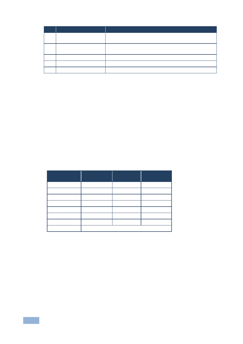
When using the RC-3TB, button 1 is always assigned to the second DISPLAY
button (button number 12) on the SL-14RC/N. The position of the rotary switch (in
the following table) determines which of the 12 buttons on the SL-14RC/N are
emulated by buttons 2 and 3 on the RC-3TB.
Rotary Switch
Position
Button 1
Button 2
Button 3
0
12
7
8
1
12
7
9
2
12
7
10
3
12
8
9
4
12
8
10
5
12
9
10
6
12
7
9
7
Service use only
For example, if the rotary switch is in position 4, the 3 buttons on the RC-3TB will
duplicate the functions of buttons 12, 8, and 10 on the SL-14RC/N. That is, in this
example, pressing button 1 on the RC-3TB has the same effect as pressing button
12 on the SL-14RC/N, pressing button 2 on the RC-3TB has the same effect as
pressing button 8 on the SL-14RC/N, and pressing button 3 on the RC-3TB has
the same effect as pressing button 10 on the SL-14RC/N.