2 defining the rc-3tbu remote control panel, Defining the rc-3tbu remote control panel, Figure 4: rc-3tbu remote control panel components – Kramer Electronics RC-3TBU User Manual
Page 12
SL-14RC/N - Defining the Remote Control Panels
9
Note: The rotary switch configuration is only read at switch on. Therefore, when
changing the rotary switch position, you must switch off the SL-14RC/N and then
switch it on again for the new settings to take effect.
For connecting the RC-3TB, see
Section 7.3
5.2
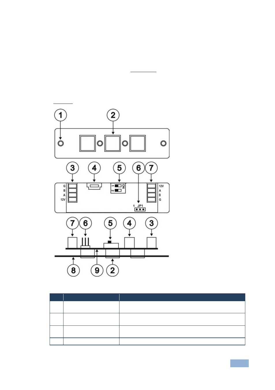
Defining the RC-3TBU Remote Control Panel
defines the RC-3TBU.
Figure 4: RC-3TBU Remote Control Panel Components
#
Feature
Function
1
Mounting Holes
2 holes for mounting the RC-3TBU to the PTBUS-3 or
TBUS-6W
2
Buttons 1 to 3
Function assignment is performed using the configurator
software
3
K-NET Connector
Connect to either SL-14RC/N or additional RC-3TB/U
devices
4
USB Connector
For connecting to the programming PC