Kramer Electronics VP-790 User Manual
Page 13
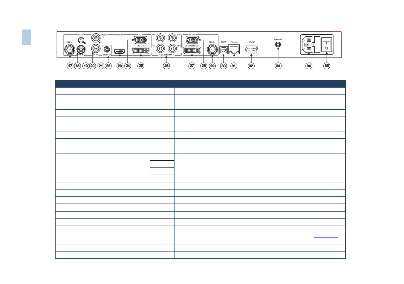
Figure 2: VP-790 Genlock Presentation Switcher/Scaler Rear Panel
#
Feature
Function
17
SDI IN BNC Connector
Connect to the SDI source
18
Y/C IN 4-pin Connector
Connect to the s-Video source
19
CV 2 IN RCA Connector
Connect to the composite video 2 source
20
CV 1 IN BNC Connector
Connect to the composite video 1 source
21
GENLOCK IN BNC Connector
Connect to an external genlock input
22
S/PDIF OUT RCA Connector
Connect to a digital audio acceptor
23
HDMI Connector
Connect to the HDMI source
24
PC IN 15-pin HD Connector
Connect to the computer graphics source
25
DVI IN DVI-I Connector
Connect to the DVI source
26
RGB/COMPONENT IN BNC
Connectors
S
Connect to the RGBS/component video source
R/Pr
G/Y
B/Pb
27
DVI-D/HDMI OUT DVI Connector
Connect to the DVI/HDMI acceptor
28
PC OUT 15-pin HD Connector
Connect to a VGA acceptor
29
SDI OUT BNC Connector
Connect to an SDI acceptor
30
PROG USB Connector
Connect to a PC for firmware upgrade
31
ETHERNET Connector
Connects to the PC or other Serial Controller through computer networking
32
RS-232 9-pin D-sub Port
Connect to the PC or the remote controller
33
REMOTE IR Opening (Covered by a cap. The
3.5mm connector at the end of the internal IR
connection cable fits through this opening)
Connects to an external IR receiver unit for controlling the machine via an IR
remote controller instead of using the front panel IR receiver (see
Section
34
Power Connector with Fuse
AC connector, enabling power supply to the unit
35
POWER Switch
Illuminated switch for turning the unit ON or OFF
8
VP
-7
9
0
–
Ov
e
rv
ie
w