Kramer Electronics VS-808TP User Manual
Page 9
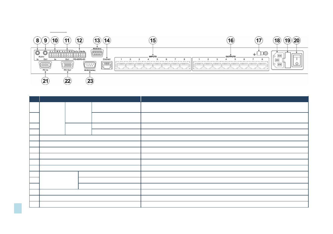
defines the rear panel of the VS-808TP.
Figure 2: VS-808TP 8x8 Twisted Pair Matrix Switcher Rear Panel
#
Feature
Function
8
AUDIO
Connectors
Unbalanced
IN 3.5mm mini jack
Connect to the output of the unbalanced stereo audio source (for example, the audio output
of the laptop)
9
OUT 3.5mm mini jack
Connect to the input of the unbalanced stereo audio acceptor (for example, the audio input of
the AV system)
10
Balanced
IN 5-pin terminal block
Connect to the output of the balanced stereo audio source
11
OUT 5-pin terminal block
Connect to the input of the balanced stereo audio acceptor
12
RS-485/RS-422 5-Pin Terminal Block
Connect to the serial controller
13
RS-232 (DATA) 9-pin D-sub Connector
Connect to the serial data source
14
ETHERNET RJ-45 Connector
Connect via a LAN to the Ethernet port on the PC controller
15
INPUTS 1 ~ 8 RJ-45 Connectors
Connect to the TP transmitters (for example, TP-133 or TP-125)
16
OUTPUTS 1 ~ 8 RJ-45 Connectors
Connect to the TP receivers (for example, TP-134 or TP-126)
17
Chassis Ground Terminal
Terminal for grounding the chassis to the common ground of the system
18
AC Mains Module
Mains socket
Connect the mains power cord
19
Mains fuse holder
Fuse for protecting the device
20
Mains switch
Turn the device on and off
21
PC IN 15-pin HD VGA Connector
Connect to the output of the VGA (up to WUXGA) source (for example, PC graphics card)
22
PC OUT 15-pin HD VGA Connector
Connect to the input of the VGA acceptor (for example, LCD monitor)
23
RS-232 (CONTROL) 9-pin D-sub Connector
Connect to the serial controller
VS
-80
8T
P
–
D
e
fin
in
g
t
h
e
V
S
-80
8T
P
8
x8
T
w
ist
ed
P
ai
r
Ma
tr
ix
S
w
itc
h
e
r
5