11 kramer protocol, 1 kramer protocol 2000, Kramer protocol – Kramer Electronics VS-808TP User Manual
Page 30: Kramer protocol 2000
26
VS-808TP - Kramer Protocol
11
Kramer Protocol
The VS-808TP supports the Kramer Protocol 2000.
You can download our user friendly “Software for Calculating Hex Codes for Protocol 2000”
from the technical support section
11.1 Kramer Protocol 2000
This RS-232/RS 485/Ethernet communication protocol (Version 0.51) uses four
bytes of information as defined below. For serial communication parameters, see
Section 10.1
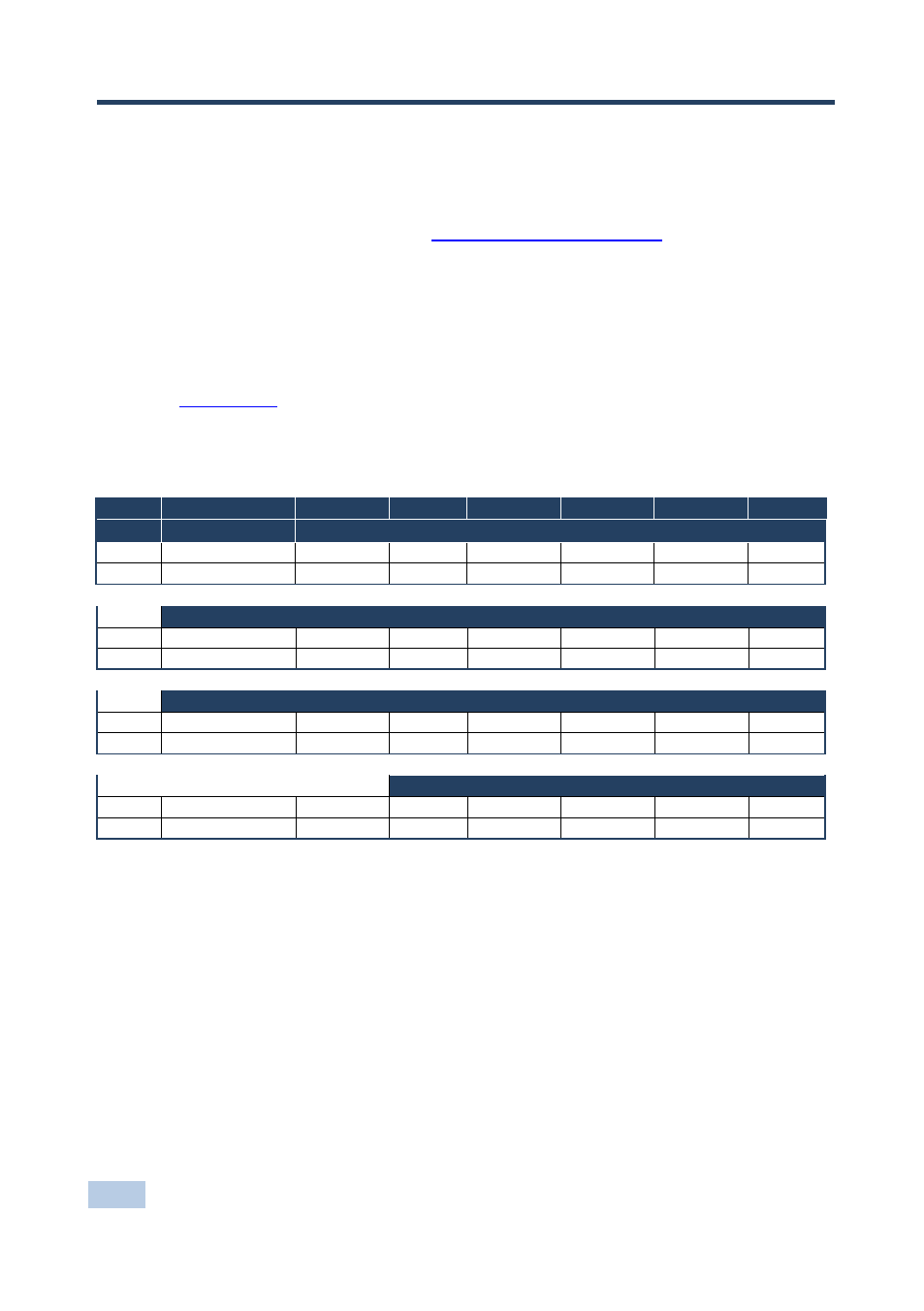
Table 1: Protocol Definitions
MSB
LSB
DESTINATION
INSTRUCTION
0
D
N5
N4
N3
N2
N1
N0
7
6
5
4
3
2
1
0
1st byte
INPUT
1
I6
I5
I4
I3
I2
I1
I0
7
6
5
4
3
2
1
0
2nd byte
OUTPUT
1
O6
O5
O4
O3
O2
O1
O0
7
6
5
4
3
2
1
0
3rd byte
MACHINE NUMBER
1
OVR
X
M4
M3
M2
M1
M0
7
6
5
4
3
2
1
0
4th byte
1
st
BYTE:
Bit 7 – Defined as 0.
D – “DESTINATION”:
0 - for sending information to the switchers (from the PC);
1 - for sending to the PC (from the switcher).
N5…N0 – “INSTRUCTION”
The function that is to be performed by the switcher(s) is defined by the INSTRUCTION (6 bits). Similarly, if a function is
performed via the machine’s keyboard, then these bits are set with the INSTRUCTION NO., which was performed. The
instruction codes are defined according to the table below (INSTRUCTION NO. is the value to be set for N5…N0).
2
nd
BYTE:
Bit 7 – Defined as 1.
I6…I0 – “INPUT”.
When switching (ie. instruction codes 1 and 2), the INPUT (7 bits) is set as the input number which is to be switched.
Similarly, if switching is done via the machine’s front-panel, then these bits are set with the INPUT NUMBER which was
switched. For other operations, these bits are defined according to the table.
3
rd
BYTE:
Bit 7 – Defined as 1.
O6…O0 – “OUTPUT”.