Kramer Electronics VS-3232A User Manual
Page 29
KRAMER: SIMPLE CREATIVE TECHNOLOGY
VS-3232A 32x32 Audio Matrix Switcher Configurations
24
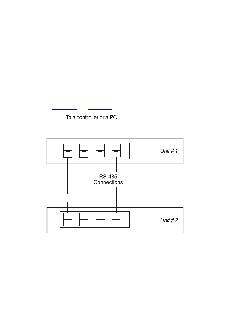
To connect an RS-485 connector on one VS-3232A unit to an RS-485
connector on one or more video switchers (from the series of 32x32 or 16x16
matrix switchers), as
1. Connect the “A” PIN on the first VS-3232A unit to the “A” PIN on the
VS-3232Vxl unit and to all the other video units.
2. Connect the “B” PIN on the first VS-3232A unit to the “B” PIN on the
VS-3232Vxl unit and to all the other video units.
3. If shielded twisted pair cable is used, the shield may be connected to the “G”
(Ground) PIN
If necessary (for a video-audio combination only), connect the SYNC pins
together. For details about how to configure the vertical sync (if required),
refer to
Section 7.7
Section 9.2
Vertical Sync
Syn
c
G
A
B
Figure 17: Connecting the RS-485 Connectors between VS-3232A/VS-3232V(xl) Units
Figure 18 illustrates the RS-485 line that connects:
• Between the VS-3232Vxl and VS-3232A unit
• To the PC via a Kramer TOOLS VP-43xl Interface Converter (connect the
9-pin D-sub COM port of the PC to the RS-232 IN 9-pin D-sub F port on
the VP-43xl and then connect the RS-485 port on the VP-43xl to the
RS-485 ports on the switcher units)