5 dip-switch settings, Dip-switch settings, Figure 14: dip-switches – Kramer Electronics VS-3232A User Manual
Page 25: Table 6: dip-switch definitions, N 7.5, Set the dip-switches as follows
KRAMER: SIMPLE CREATIVE TECHNOLOGY
VS-3232A 32x32 Audio Matrix Switcher Configurations
20
Set the DIP-switches as follows:
Table 5: DIP-switch Settings for VS-3232A and VS-3232V(xl) Switchers
Machine Name
Machine #
Follow-System
Master/Slave
1
2
3
4
5
6
VS-3232V(xl) Y (G)
ON
OFF
OFF
OFF
ON
OFF
U (B)
ON
OFF
OFF
OFF
ON
ON
V (R)
ON
OFF
OFF
OFF
ON
ON
VS-3232A
Audio
OFF
ON
OFF
OFF
ON
OFF
Connect the communication line between the switchers via the RS-232 or
RS-485 control interface as section 7.6 describes.
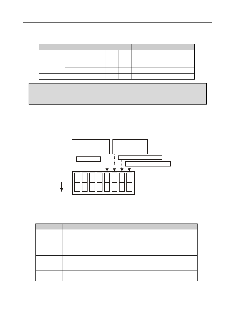
7.5 DIP-switch Settings
By default all the DIP-switches are set to OFF. Configure the VS-3232A by
setting the eight DIP-switches as
1 2
ON
3 4 5 6 7 8
}
RS-232 NULL-MODEM
MACHINE #
FOLLOW-SYSTEM
CONFIGURATION
SETUP
MASTER/SLAVE
CONFIGURATION
SETUP
RS-485 TERMINATION
Figure 14: DIP-switches
Table 6: DIP-switch Definitions
DIP-switch #
Function:
1-4
Set the machine # (see
Section 7.5.1
5
Enables (ON) or disables (OFF) the Follow-System configuration setup in a
multi-switcher configuration
6
Enables (ON) or disables (OFF) the Master/Slave configuration setup in a
multi-channel configuration
7
Disables the use of a null modem adapter
1
with RS-232 as follows:
Set OFF for RS-232 input connection via a null modem adapter
Set ON for RS-232 straight connection without a null modem adapter
8
Set ON for RS-485 termination for the first and the last machine (RS-485 line
terminates with 110
Ω); for others set OFF (RS-485 line is open)