2 connecting two vs-3232a units via rs-232, 2 connecting the rs485 control interface, Connecting the rs-485 control interface – Kramer Electronics VS-3232A User Manual
Page 28: Figure 16: rs-485 connector pinout
VS-3232A 32x32 Audio Matrix Switcher Configurations
23
23
To connect a PC to the VS-3232A unit, without using a Null-modem adapter:
1. Connect the RS-232 9-pin D-sub port on your PC to the RS-232 IN 9-pin
D-sub rear panel port on the Master VS-3232A with a 9-wire cable
1
to the
RS-232 9-pin D-sub port on your PC.
2. Set DIP 7 ON
2
(disabling Null-modem adapter use) on the VS-3232A unit.
7.6.1.2
Connecting two VS-3232A Units via RS-232
To connect two VS-3232A units, using a Null-modem adapter provided with
the machine (the default):
1. Connect a cable between the RS-232 OUT 9-pin D-sub port on the first
VS-3232A unit and the Null-modem adapter that attaches to the RS-232 IN
9-pin D-sub port on the second VS-3232A unit.
2. On the second VS-3232A unit, set DIP 7 OFF
(enabling Null-modem
adapter use).
To connect two VS-3232A units, without using a Null-modem adapter:
1. Connect a cable between the RS-232 OUT 9-pin D-sub port on the first
VS-3232A unit and the RS-232 IN 9-pin D-sub port on the second
VS-3232A unit.
2. On the second VS-3232A unit, set DIP 7 ON (disabling Null-modem
adapter use).
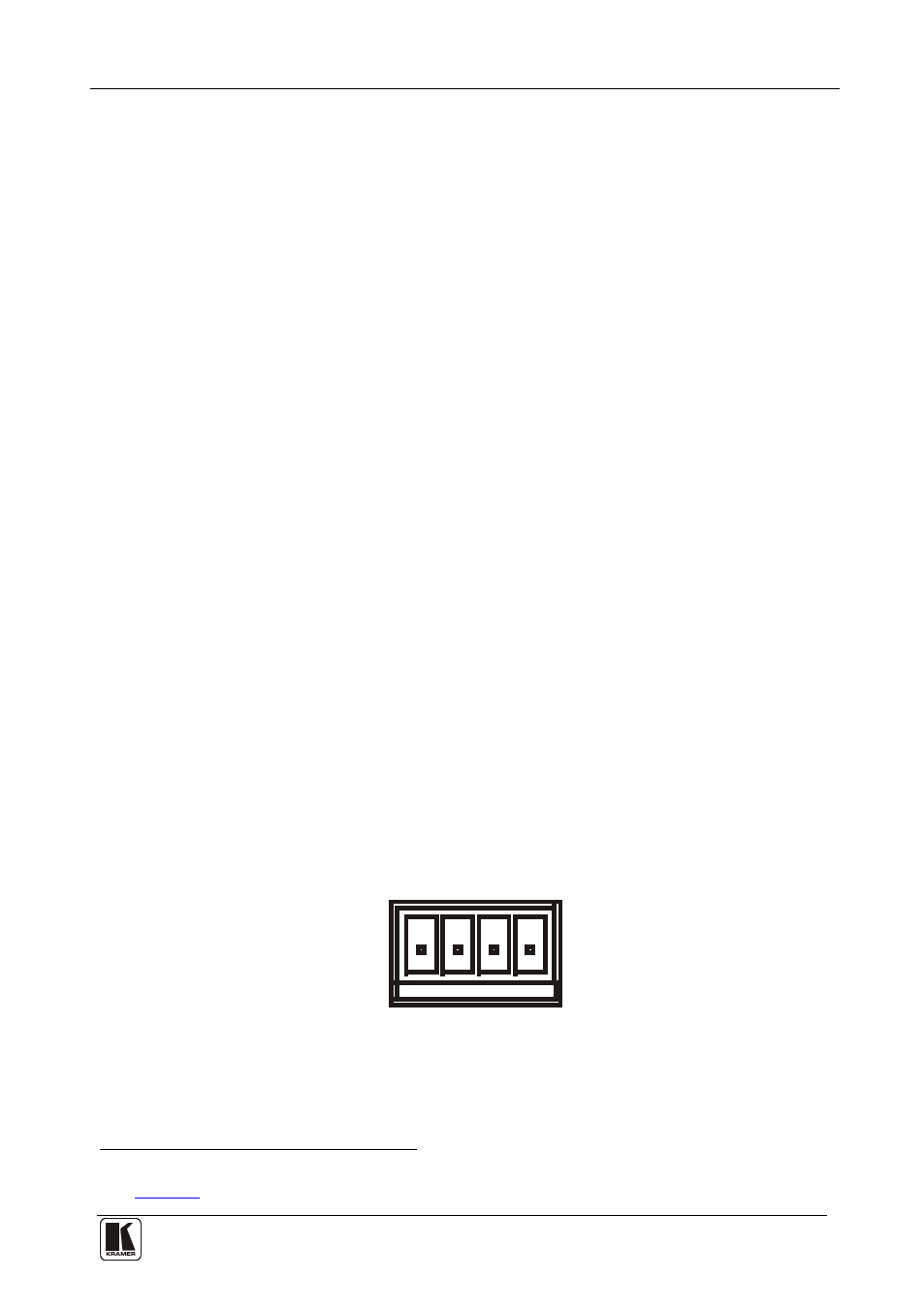
7.6.2 Connecting the RS-485 Control Interface
Figure 16 defines the RS-485 connector PINOUT for external RS-485 control.
The RS-485 connector is also used (if required) for vertical sync. The A and B
PINs are for RS-485, and the SYNC and the G PINs are for vertical sync and
ground connection, respectively
SYNC G B A
RS-485
Figure 16: RS-485 Connector PINOUT
1 The cable should consist of at least three straight-through wires – PINs 2, 3 and 5 – and PINs 2 and 3 should be crossed
2 See