Kramer Electronics VP-31 User Manual
Page 12
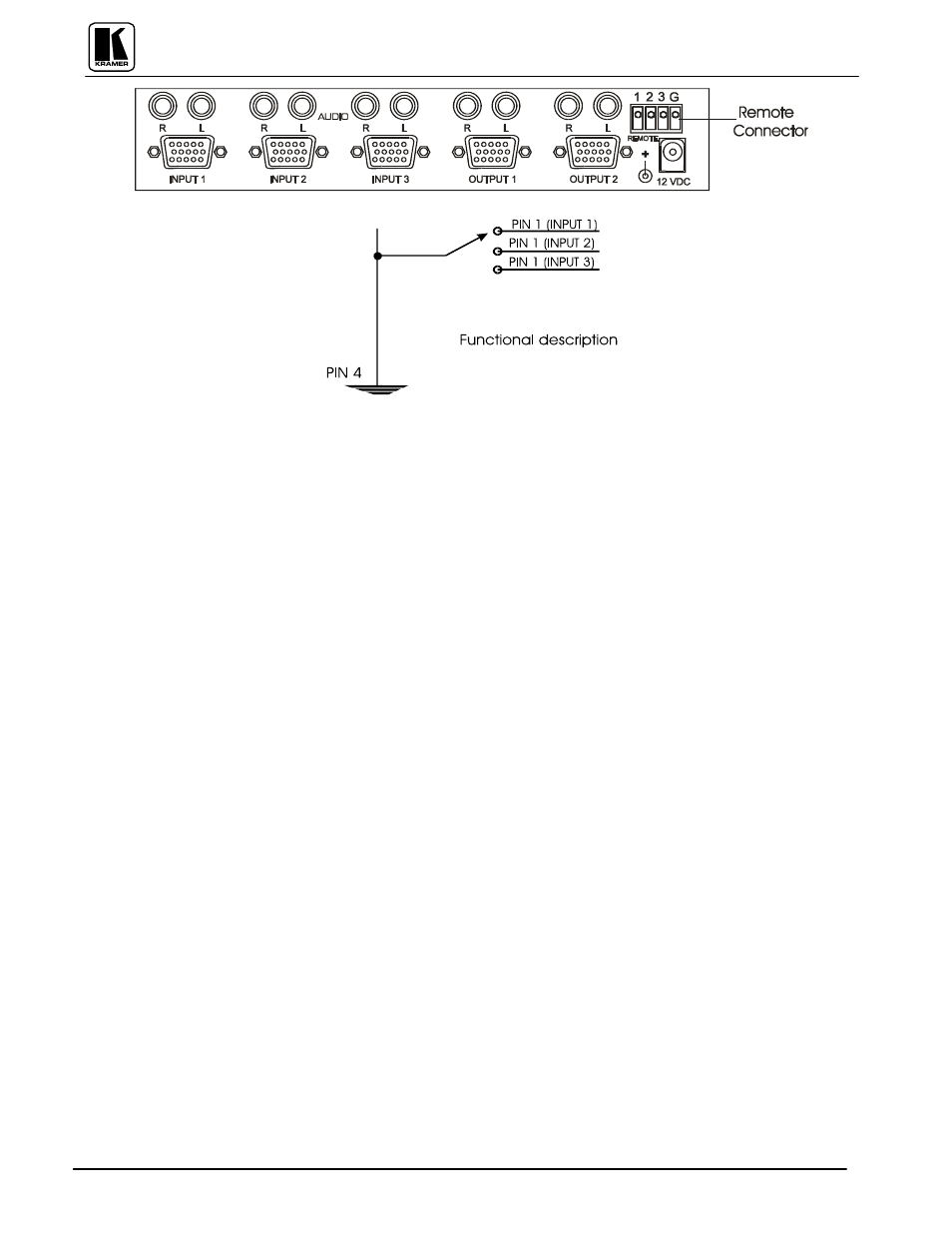
Figure 4: VP-32xl Remote Connector Location and Pinout
Controlling the VP-61RS
The VP-61RS switcher can be controlled by the following methods:
1) By touch buttons on the front panel (see section 9.2 "Selecting an Input on the Switchers").
2) By any RS-232 controller such as a PC or the VS-2000 (for more information, refer to Section 9.4.1: The
VS-2000 System") which is programmed according to the protocol of the switcher (see Section 13:
“Protocol Used for VP-61RS Communication").
9.4.1
The VS-2000 System
The KRAMER VS-2000 is a Programmable Remote Control Unit, designed for use in video production and
duplication studios and in live broadcasting and editing configurations. It provides access to and control of up
to six groups of KRAMER switchers from a single point. A group can comprise several interconnected
switchers which, in turn, permit access to various pieces of equipment (monitors, mixers, editors, VCRs, etc).
The VS-2000 can be controlled by pressing its front panel touch buttons, and via a PC using the RS-232
control port. KRAMER PC control software is provided with the VS-2000. Since new switcher types are
constantly being added and older types upgraded, KRAMER provides a small door marked "EPROM" on the
VS-2000 rear panel for easy replacement of the existing chip with an updated chip. This contains the
appropriate information for the new and modified switchers. KRAMER makes updated chips available
periodically. The VS-2000 stores and recalls preferred configurations for convenience in studio control. A
typical VS-2000 system setup using the VP-61RS is shown in Figure 5. To connect and operate the VS-2000
System perform the following steps (for more details about the VS-2000 refer to the instruction manual
provided with the VS-2000).
1) Connect up to six switchers via RS-232 ports on each machine to the connectors on the rear panel of the
VS-2000 marked "
Port 1" to "Port 6" using straight DB9 to DB9 male to male flat cable.
2) Connect a PC equipped with a serial port to the socket marked "
TO PC
" on the rear panel of the VS-2000,
using a null modem connection (the null modem adapter provided with the machine). Use a straight DB9
to DB9 connector if you are using the null modem adapter, or connect as in Figure 7.
3) Connect a 12VDC power supply to the 12VDC socket on the rear panel of the VS-2000. Use a DC wall
transformer with a positive center pin.
4) Turn on all the machines and the VS-2000.
5) To install the software provided with the distribution diskette for PC control, copy the contents of the
diskette into a sub directory on your hard disk and read the
BC-2000.HLP file. You can print it for later
reference. The file name
BC20PROT.HLP
is the communication protocol for advanced users.