Caution, Installation of back pull-out assembly – Goulds Pumps 3910 11th ed. - IOM User Manual
Page 78
$
CAUTION
Do not allow coupling halves or other components to
make contact, as damage to coupling and/or other
components could result.
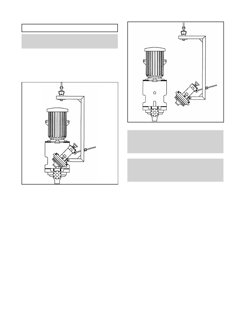
9.
Tighten coupling nut on threaded rod to tilt top of back
pull-out assembly towards upright of removal device
(Fig III-E).
10. Repeat steps 8 and 9 until seal chamber cover/ stuffing
box cover (184) aligns with cutout in motor support
(240) and coupling clears top flange of motor support.
11. Move bearing frame assembly/removal device
assembly horizontally until clear of motor support
(240) (Fig III-F).
NOTE: In some cases, it may be necessary to loosen
the coupling guard end plate from the thrust bearing
end cover to gain sufficient clearance. Follow
coupling guard installation and disassembly
instructions in Appendix I.
NOTE: With experience, maintenance personnel will
understand the interactions between vertical and
rotational movements of the bearing frame
assembly/removal device assembly and will make
adjustments appropriately.
12. Follow the remaining instructions in Disassembly.
INSTALLATION OF BACK
PULL-OUT ASSEMBLY
Reverse steps in Removal of Back Pull-Out Assembly,
previously described in this appendix.
78
3910-
11th IOM 5/08
Fig III-E
Fig III-F