Goulds Pumps 3910 11th ed. - IOM User Manual
Page 22
LUBRICATING BEARINGS
!
Bearings musts be lubricated properly in order to
prevent excess heat generation, sparks and
premature failure.
Grease Lubrication
Greased lubricated ball bearings are standard on the Model
3910 units.
The bearings are greased at the factory.
See Preventive Maintenance section for lubrication
recommendations.
Pure Oil Mist Lubrication
Pure oil mist is an optional feature for the Model 3910.
Follow oil mist generator manufacturer’s instructions. The
inlet and outlet connections are located on the side of the
bearing frame.
See Preventive Maintenance section for lubrication
recommendations and connection locations.
s
!
WARNING
Operation of the unit without proper lubrication will
cause bearing failure and pump seizure.
SHAFT SEALING WITH
MECHANICAL SEAL
!
The mechanical seal used in an ATEX classified
environment must be properly certified.
Pumps may be shipped with or without mechanical seal
installed. Cartridge type mechanical seals are commonly
used for this model. Cartridge seals are preset at the seal
manufacturer’s facility and require no field settings.
Cartridge seals installed by the user require disengagement
of the holding clips prior to operation, allowing the seal to
slide into place. If the seal has been installed in the pump
by Goulds, these clips have already been disengaged. For
other types of mechanical seals, refer to the seal
manufacturer’s instructions for installation and setting.
Connection of Sealing Liquid
!
The mechanical seal must have an appropriate seal
flush system. Failure to do so will result in excess heat
generation and seal failure.
!
Cooling systems such as those for bearing
lubrication, mechanical seal systems, etc., where
provided, must be operating properly to prevent
excess heat generation, sparks, and premature
failure.
!
Sealing systems that are not self purging or self
venting, such as plan 23, require manual venting
prior to operation. Failure to do so will result in
excess heat generation and seal failure.
For satisfactory operation, there must be a liquid film
between seal faces to lubricate them. Refer to seal
manufacturer’s drawing for location of taps. Some methods
which may be used to flush/cool the seal are:
•
Product Flushing - In this arrangement, the pumpage is
piped from the casing (and cooled in an external heat
exchanger when required) then injected into seal
chamber.
•
External Flush - A clean, cool compatible liquid is
injected from an outside source directly into seal
chamber. Flushing liquid must be at a pressure 0.35-1.05
kg/cm
2
(5-15 psi) greater than seal chamber pressure. Injection
rate should be 2-8 l/min. (
1
2
-2 GPM).
•
Other methods may be used which make use of multiple
gland connections and/or seal chamber connections.
Refer to documentation supplied with the pump,
mechanical seal reference drawing, and piping diagrams.
PRIMING PUMP
!
Pumps must be fully primed at all times during
operation.
Never start the pump until it has been properly primed.
Several different methods of priming can be used, depending
upon type of installation and service involved.
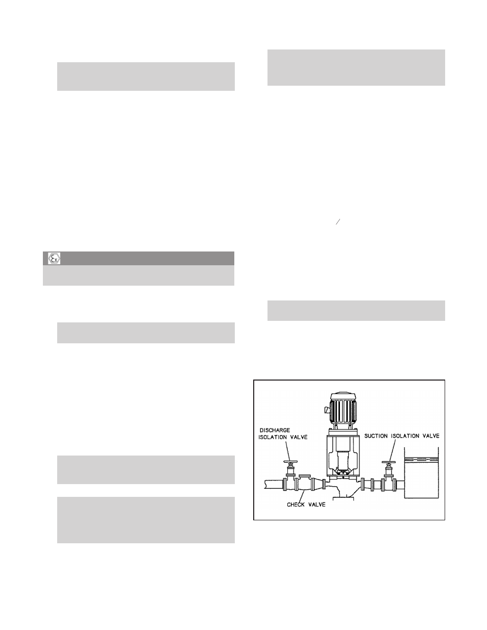
Suction Supply Above Pump
1.
Slowly open the suction valve (Fig. 8).
2.
Open air vents on the suction and discharge piping, casing,
seal chamber, and seal piping, if provided, until all air is
vented and only liquid flows out.
3.
Close the vents.
22
3910-1
1th IOM 5/08
Fig. 8