Caution – Goulds Pumps 3910 11th ed. - IOM User Manual
Page 47
14. Install thrust bearing end cover (109A) over shaft
(122) and onto bearing frame (228). For SA pumps,
install thrust cover with the words “Top oil mist” on
top.
15. Install and tighten thrust bearing end cover/bearing
frame screws (370N) evenly to torque valves shown in
Table 7.
$
!
CAUTION
Do not over tighten thrust bearing end cover/ bearing
frame screws.
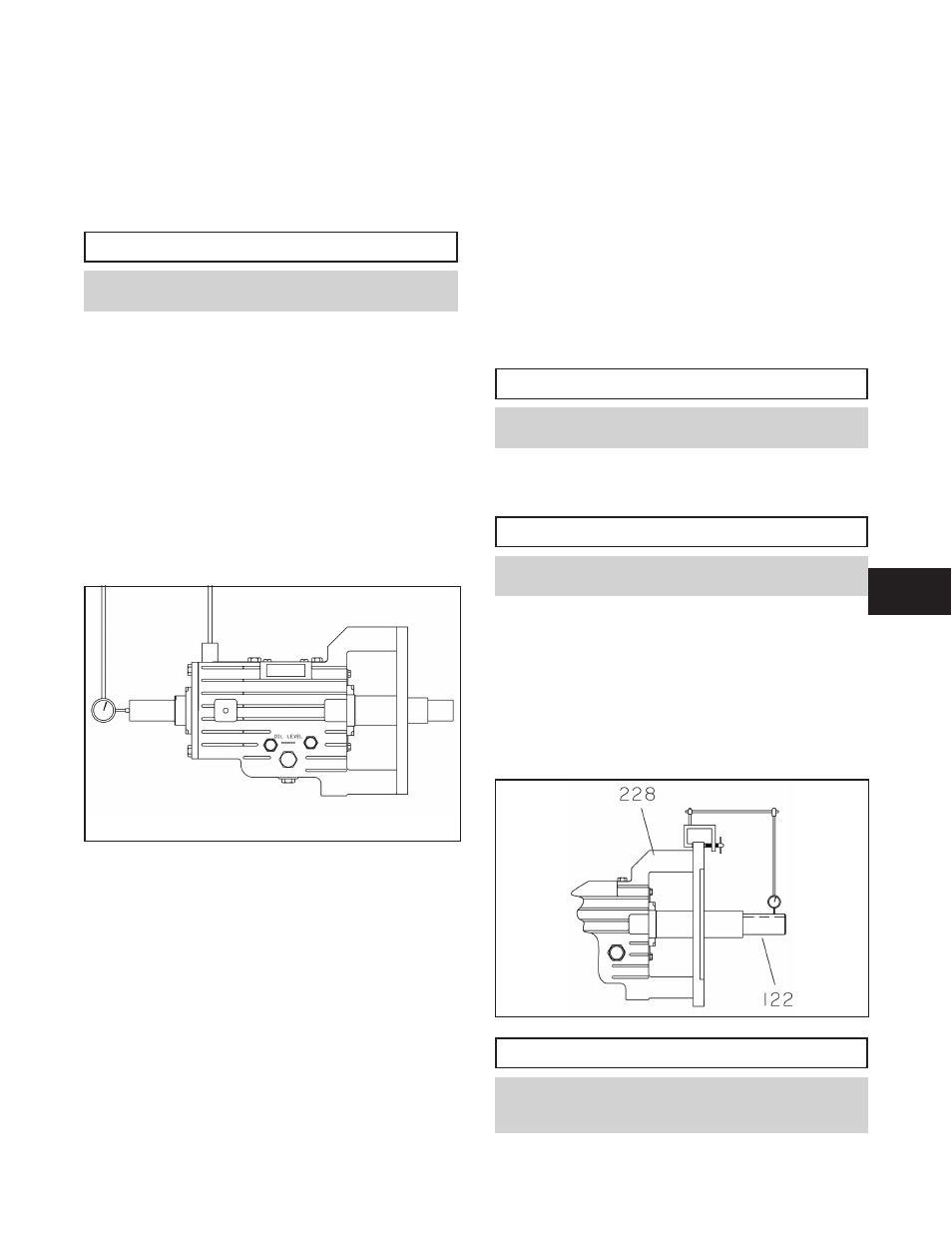
16. Determine axial end play as follows:
a.
Mount dial indicator as shown in Fig. 43.
b.
Apply axial force to impeller end of shaft (122)
and firmly seat thrust bearing (112) against
shoulder in bearing frame (228).
c.
Apply axial force in opposite direction and firmly
seat thrust bearing (112) against thrust bearing end
cover (109A).
d.
Repeat steps b and c several times and record total
travel (end play) of rotating element.
e.
Total travel (end play) must fall in the range of
0.025 to 0.125 mm (0.001 to 0.005 inches).
17. The axial end play is achieved by adding or removing
end cover gaskets (360C) for SA pumps or end cover
shims (390C) between the thrust bearing end cover
(109A) and the bearing frame (228). Add
gaskets/shims if no axial end play is present.
18. Repeat steps 13 - 16. Total travel (end play) should
fall in the range of 0.025 - 0.125 mm
(.001 - .005 in.). If the measured total travel falls
outside this range, remove or add the appropriate
quantity of individual shims to obtain the proper total
travel. For SA pumps, skip steps 19 through 22.
19. Remove thrust bearing end cover (109A).
20. Press INPRO (123A) into thrust bearing end cover
(109A). Ensure expulsion port is at 6 o'clock position
and is properly seated.
21. Install O-ring (412, not shown) into groove in thrust
bearing end cover (109A) (N/A on SA pumps).
22. Lubricate O-ring (412) with a suitable lubricant.
23. Install thrust bearing end cover (109A) with O-ring
(412) over shaft (122) and into bore of bearing frame
(228). Ensure that O-ring is not damaged while
entering bore in frame.
24. Install and tighten thrust bearing end cover/ bearing
frame screws (370N) evenly to torque values shown in
Table 7.
$
CAUTION
Do not over tighten thrust bearing end cover/ bearing
frame screws.
25. Check shaft (122) for free turning. If rubbing or
excessive drag is detected, determine cause and
correct.
$
CAUTION
For runout checks, firmly support bearing frame
assembly in horizontal position, as shown in Fig. 36.
26. Check shaft (122) impeller fit runout in the following
manner:
a.
Mount dial indicator on bearing frame (228) as
shown in Fig. 44.
b.
Rotate shaft (122) through maximum arc from one
side of keyway to the other. If total indicator
reading is greater than 0.050 mm (.002 in.),
determine cause and correct.
$
CAUTION
Avoid turning shaft so that dial indicator contacts
keyway. Readings will be incorrect and damage to dial
indicator could result.
3910-1
1th IOM 5/08
47
Fig. 43
Fig. 44
6