Goulds Pumps 3910 11th ed. - IOM User Manual
Page 45
3910-1
1th IOM 5/08
45
ASSEMBLY OF STANDARD GREASE
LUBRICATED POWER END
This section covers assembly of standard grease lubricated
power end. For power ends with optional features (pure oil
mist lubrication, bearing cooling, etc.), refer to the
appropriate section.
s
!
WARNING
Pump components are heavy. Proper methods of lifting
and securing must be employed to avoid physical injury
and/or equipment damage.
NOTE: Make sure that all parts and threads are clean
and that all directions under Inspections have been
followed.
!
Leakage of process liquid may result in creating an
explosive atmosphere. Follow all pump and seal
assembly procedures.
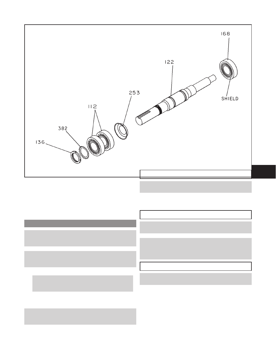
1.
Install radial (inboard) bearing (168) on shaft (122)
with shield facing shaft shoulder (Fig. 38).
NOTE: There are several methods used to install bear-
ings. The recommended method is to use an induction
heater that heats as well as demagnetizes the bearings.
$
CAUTION
Use insulated gloves when using a bearing heater.
Bearing will get hot and can cause physical injury.
2.
Install grease shelf (253) on shaft (122).
3.
Install thrust (outboard) bearings (112) on shaft (122).
$
CAUTION
The Model 3910 uses duplex bearings mounted back-to-
back. Make sure orientation of the bearings is correct.
NOTE: There are several methods used to install
bearings. The recommended method is to use an
induction heater that heats as well as demagnetizes the
bearings.
$
!
CAUTION
Use insulated gloves when using a bearing heater.
Bearings will get hot and can cause physical injury.
4.
Place bearing lockwasher (382) on shaft (122). Place
tang of lockwasher in keyway of shaft.
5.
Thread bearing locknut (136) onto shaft (122). After
bearings and shaft have cooled to ambient temperature,
tighten locknut to torque value shown in Table 7.
6.
Bend any tang of bearing lockwasher (382) into a slot of
locknut (136).
Fig. 38
6