Preliminary installation of seal chamber cover, Caution – Goulds Pumps 3910 11th ed. - IOM User Manual
Page 50
PRELIMINARY INSTALLATION OF
SEAL CHAMBER COVER
1.
Install eyebolt in tapped hole provided in seal chamber
cover (184) (Fig. 50).
2.
Rig sling to eyebolt and to overhead lifting device.
3.
Lift seal chamber cover (184) and position to align
with shaft (122).
4.
Install seal chamber cover (184) on bearing frame
assembly by guiding cover carefully over shaft (122)
and into bearing frame (228) lock.
5.
Install seal chamber cover/bearing frame bolts (370H)
and tighten evenly using alternating pattern. Torque
bolts to values shown in Table 7.
$
CAUTION
For runout checks, firmly support bearing frame
assembly in horizontal position, as shown in Fig. 36.
6.
Check seal chamber cover (184) face runout in the
following manner:
a.
Mount dial indicator on shaft (122) as shown in
Fig. 51.
b.
Rotate shaft (122) so indicator rides along the seal
chamber cover (184) gasket face for 360 degrees. If
total indicator reading is greater than 0.13 mm (.005
in.), determine cause and correct.
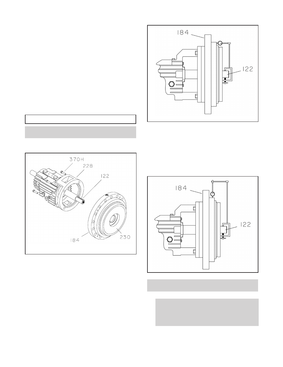
7.
Check seal chamber cover (184) lock runout in the
following manner:
a.
Mount dial indicator on shaft (122) as shown in
Fig. 52.
b.
Rotate shaft (122) so indicator rides along the seal
chamber cover (184) lock for 360 degrees. If total
indicator reading is greater than 0.13 mm (.005 in.),
determine cause and correct.
NOTE: If two dial indicators are available, steps 6
and 7 may be performed simultaneously.
!
The impeller and wear ring clearance setting
procedures must be followed. Improperly setting the
clearance or not following any of the proper
procedures can result in sparks, unexpected heat
generation, and equipment damage.
50
3910-1
1th IOM 5/08
Fig. 50
Fig. 51
Fig. 52