Appendix i-b – Goulds Pumps 3910 11th ed. - IOM User Manual
Page 67
APPENDIX I-B
INSTALLATION AND DISASSEMBLY
INSTRUCTIONS FOR GOULDS ANSI B15.1
COUPLING GUARDS
(CASING MOUNT MOTOR SUPPORT ONLY)
!
The coupling guard used in an ATEX classified
environment must be constructed from a non-
sparking material.
Power Ends with Optional
Air Cooling Package
s
!
WARNING
Before installation or disassembly of the coupling
guard is performed, the driver must be de-energized,
the driver controller/starter put in a locked-out position
and a caution tag placed at the controller/starter
indicating the disconnect. Replace coupling guard
before resuming normal operation of the pump. ITT
Industries - Goulds Pumps assumes no liability for
avoiding this practice.
Simplicity of design allows complete assembly of the
coupling guard, including the thrust end deflector fan guard
support, in about twenty minutes. If the guard support is
already in place, assembly can be accomplished in about
ten minutes. Fig. I-B-1 shows the coupling guard
components.
INSTALLATION
NOTE: If deflector fan guard support is already
installed, make any necessary coupling adjustments
and then proceed to step 11.
1.
Remove spacer portion of coupling. Refer to coupling
manufacturer’s instruction for assistance.
2.
If the coupling hub diameter is larger than the diameter
of the opening in the deflector fan guard support
(234D), remove the coupling hub.
3.
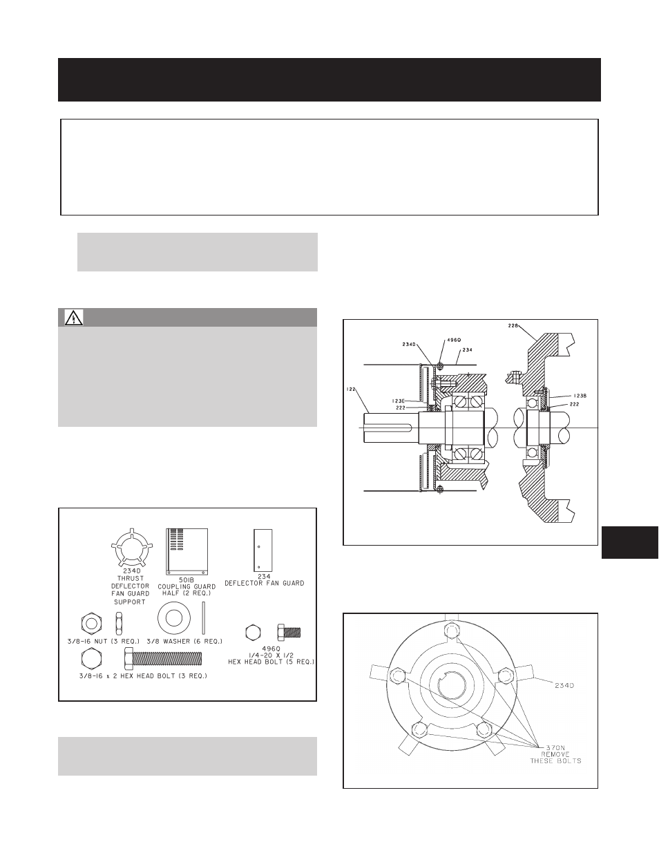
Loosen thrust deflector fan set screw (222)(Fig. I-B-2).
4.
Slide thrust deflector fan (123E) off shaft (122).
5.
Remove thrust bearing end cover/bearing frame screws
(370N) (Fig. I-B-3).
3910-
11th IOM 5/08
67
8
Fig. I-B-2
Fig. I-B-1
Fig. I-B-3