Goulds Pumps 3910 11th ed. - IOM User Manual
Page 40
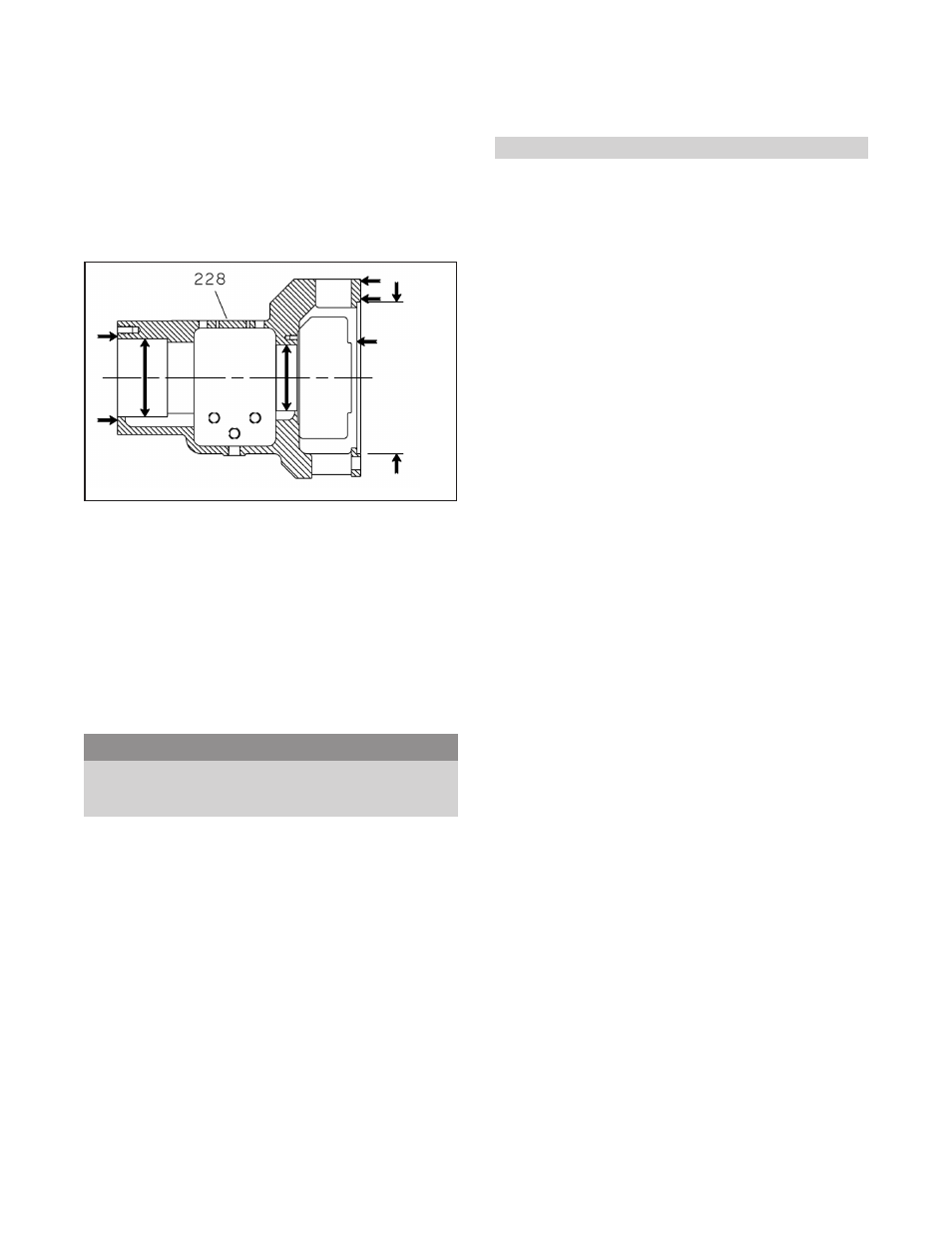
BEARING FRAME (228)
1. Visually inspect bearing frame for damage and cracks.
2. Check frame inside surfaces for rust, scale or debris.
Remove all loose and foreign material (Fig. 29).
3. Make sure all lubrication passages are clear.
4. Check bearing bores. If any are outside the tolerance
in Table 6, replace the bearing frame.
CARTRIDGE MECHANICAL SEAL
Refer to mechanial seal manufacturer’s instructions for
assistance.
Cartridge type mechanical seals should be serviced by seal
manufacturer.
COUPLING GUARD
1. Inspect guard for corrosion or other defects.
2. Replace guard or repair.
s
!
WARNING
To avoid physical injury, coupling guard must be
installed and must be maintained in first-class
condition.
GASKETS, O-RINGS, SHIMS, AND
SEATS
NOTE: Spiral wound gaskets should not be reused.
1. Replace all gaskets, O-rings and shims at each
overhaul / disassembly.
2. Inspect seats. They must be smooth and free of
physical defects. Skin cut seats in lathe as necessary,
maintaining dimensional relationships with other
surfaces. Replace parts if seats are defective beyond
reasonable repair.
GENERAL
All other parts should be inspected and repaired or
replaced, as appropriate, if inspection indicates continued
use would be harmful to satisfactory and safe pump
operation.
Inspection must include, but not be limited to, the
following:
•
Bearing End Covers (109A) and (119A)
•
INPROS (123) and (123A)
•
Radial Heat Flinger (123B)*
•
Thrust Fan (123E)*
•
Bearing Locknut (136)
•
Impeller Key (178) and Coupling Key
•
Impeller Nut (304)
•
Bearing Lockwasher (382)
•
Water Jacket Cover (490)*
•
All Nuts, Bolts and Screws
* If supplied.
40
3910-1
1th IOM 5/08
Fig. 29