Goulds Pumps 3420 - IOM User Manual
Page 76
d. Check the clearance by rotating the shaft 90
° and
measuring the clearance. Tighten the locknut, if
required. This should be done several times to ensure
the bearing is not distorted.
7.
Bend a tang of the lockwasher into a locknut groove.
8.
Oil Lubrication
a. Bolt the oil ring housings (515 and 515A) to the
bearing housings (134 and 134A) using capscrews (371T).
b. Place the oil rings (114) in the grooves on the oil
ring sleeve.
c. Bolt the end covers (109A) and 119A) to the
bearing housings using capscrews (371S). Tighten
finger tight.
d. Slide the dust cover (139) and the coupling on the shaft.
Grease Lubrication: Slide the dust cover (123A) with
the seal installed and the coupling on the shaft.
D. LDS and XL Group
1.
Oil Lubrication
*a. Slide the oil throwers (123) on the shaft (122).
b. Install the bearing end covers (109B and 119B) on
the bearing housings (134 and 134A) with capscrews
(370). Tighten the capscrews to the torque value
shown in Table 11.
c. Slide the bearing housing sub-assemblies on the shaft.
Grease Lubrication
*a. Slide the deflectors (333) on the shaft (122).
*b. Install the grease seals (333) in the inboard
bearing end covers (109B and 119B).
c. Install the bearing end covers on the bearing
housings (134 and 134A) with capscrews (370).
Tighten the capscrews to the torque value shown in
Table 11.
d. Slide the bearing housing sub-assemblies on the
shaft.
2.
Slide the roller bearings (409 and 410) on the shaft
until they contact the shaft shoulder.
NOTE: The inner race of the roller bearing has a
tapered bore. Make sure the large bore end of the
bearing faces the end of the shaft. The lip of the adapter
sleeve slides under the inner race of the bearing.
3.
Lightly oil the shaft and the outside diameter of the
adapter sleeve. Slide the lip of the sleeve under the
inner race of the bearing.
4.
Slide the oil ring sleeves (324) on the shaft.
5.
Place the bearing lockwashers (382) and the bearing
locknuts (136) on the shaft and tighten finger tight.
6.
L, LDS, XL, and XXL frames use spherical roller
bearings mounted on tapered sleeves which require
tightening of the bearing locknut to draw the bearing
up on the taper. Correct tightening of the locknut is
accomplished by measuring the clearance before and
after tightening to arrive at a given change in bearing
clearnace. Once this change in clearance has been
reached, the bearing is correctly mounted on the
sleeve. The minumum clearance after tightening
should also not be less than the given value. The
following steps describe how this is accomplished:
a.
With the bearing axis horizontal and no upward force
on the bearing outer race, rotate the inner race such
that a set of rollers is at the bottom. Measure the
clearance between the bottom roller OD and the ID of
the bearing outer race using a feeler gauge. Record
this value.
b.
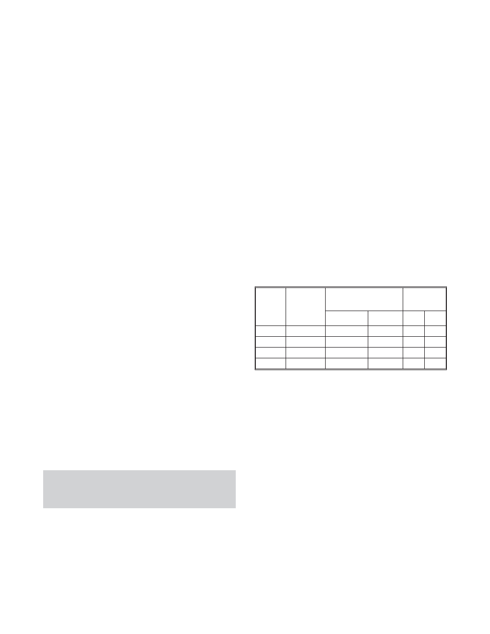
Tighten the locknut (136) until a reduction
(measurement from Step 6a minus the measurement
after tightening of the locknut) in bearing clearance is
reached as given below. Also, verify the minimum
clearance is not less than the value given below.
Rotate the bearing through 90 degree increments and
verify the clearance in a few positions.
Group
SKF
Bearing
Size
Clearance
Reduction
Minimum
Clearance
Inches
mm
In.
mm
L
22226 CN
.0025-.0035
.065-.09
.002
.055
LDS
22228 CN
.0025-.0035
.065-.09
.002
.055
XL
22230 CN
.003-.004
.075-.10
.0022
.06
XXL
22240 CN
.0032-.0043
.08-.11
.0024
.06
7.
Bend a tang of the lockwasher into a locknut groove.
8.
Oil Lubrication
a. Bolt the bearing housings (134 and 134A or 134D
and 134A) to the bearing end covers (109A and 119B)
using capscrews (370 or 371C). Tighten the
capscrews to the torque shown in Table 11.
b. Place the oil rings (114) in the grooves on the oil
ring sleeve.
c. Bolt the end covers (109A and 119A) to the
bearing housings using capscrews (370 or 371C).
Tighten finger tight.
*d. Slide the dust cover (123A) and the coupling on
the shaft.
*
These parts are replaced by the optional labyrinth
seals (332 Opt), 333 Opt) when so equipped. Do not
separate the rotor from the stator with labyrinth style
seals.
72
3420 IOM 8/09