Goulds Pumps 3420 - IOM User Manual
Page 104
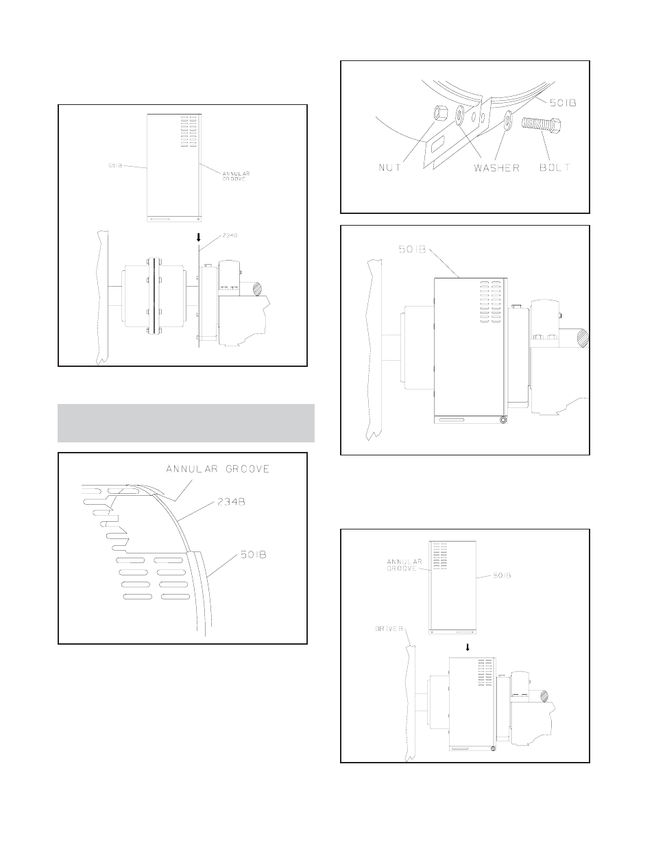
7.
Spread opening of coupling guard half (501B) slightly
and place over pump end plate (234B) as shown in
Fig. I-C.
The annular groove in the guard is located around the end
plate as indicated in Fig. I-D.
NOTE: Locate opening (flange) so that it will not
interfere with piping but will allow access for installing
bolts (Step 8).
8.
Placed one washer over bolt and insert bolt through
round hole at front end of guard half (501B).
9.
Place a second washer over exposed end of bolts.
10. Thread nut onto exposed end of bolt end, tighten
firmly.
The proper sequence of components is shown in Fig. I-E;
an assembled unit is shown in Fig. I-F.
11. Spread opening of remaining coupling guard half
(501B) slightly and place over installed coupling
guard half so that annular groove in remaining
coupling guard half faces the driver as indicated in
Fig. I-G.
100
3420 IOM 8/09
Fig I-C
Fig I-D
Fig I-E
Fig I-F
Fig I-G
- 3100 - IOM (52 pages)
- 3171 - IOM (60 pages)
- 3180-86 - IOM (158 pages)
- 3189 - IOM (32 pages)
- 3196 - IOM (148 pages)
- 3196 i-FRAME - IOM (152 pages)
- 3198 i-FRAME - IOM (126 pages)
- 3296 EZMAG - IOM (96 pages)
- 3296M - IOM (92 pages)
- 3298 - IOM (120 pages)
- 3311 - IOM (44 pages)
- 3316 - IOM (36 pages)
- 3335 - IOM (40 pages)
- 3355 - IOM (66 pages)
- 3393 - IOM (124 pages)
- 3408 - IOM (78 pages)
- 3408A - IOM (44 pages)
- 3409 - IOM (68 pages)
- 3410 - IOM (56 pages)
- 3498 - IOM (59 pages)
- 3500XD - IOM (44 pages)
- 3501 Mixer - IOM (48 pages)
- 3600 - IOM (110 pages)
- 3610 - IOM (98 pages)
- 3620 - IOM (98 pages)
- 3640 - IOM (98 pages)
- 3642 - IOM (12 pages)
- 3675 - IOM (12 pages)
- 3700 - IOM (110 pages)
- 3755 - IOM (32 pages)
- 3796 i-FRAME - IOM (134 pages)
- 3910 11th ed. - IOM (80 pages)
- 3935 - IOM (24 pages)
- 3996 - IOM (52 pages)
- 4550 - IOM (36 pages)
- 5000 - IOM (24 pages)
- 5100 - IOM (28 pages)
- 5150 - IOM (28 pages)
- 7200CB - IOM (132 pages)
- ANSI FAMILY IOM (ATEX Compliant) (56 pages)
- ANSI FAMILY IOM (ATEX Compliant) (27 pages)
- ANSI FAMILY IOM (ATEX Compliant) (42 pages)
- ANSI FAMILY IOM (ATEX Compliant) (45 pages)
- Pump Safety (9 pages)