Disassembly, Warning – Goulds Pumps 3420 - IOM User Manual
Page 105
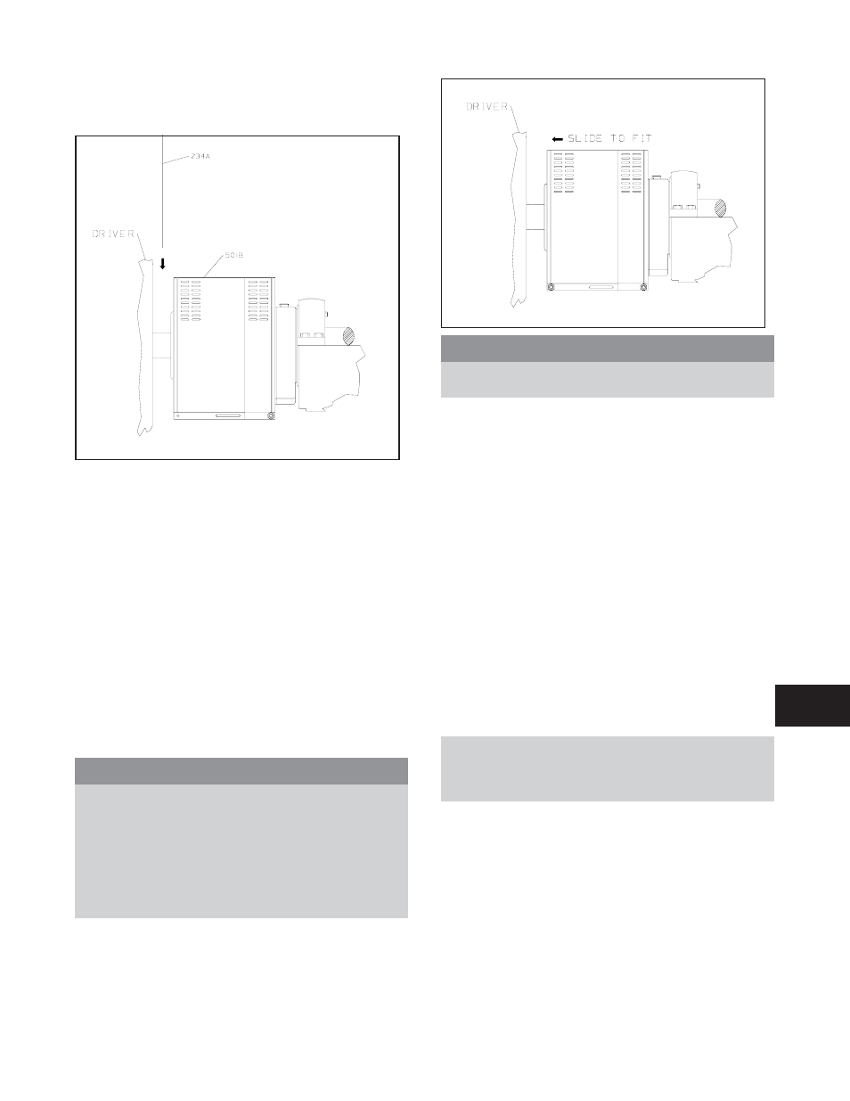
12. Place end plate (234A) over driver shaft as indicated
in Fig. I-H. Locate the end plate in the annular
groove at the rear of the coupling guard half (501B).
13. Repeat steps 8-10 for rear end of coupling guard half
(501B), except that nut should be finger tightened
only.
14. Adjust length of coupling guard to completely cover
shaft and coupling as shown in Fig. I-I by sliding rear
coupling guard half (501B) towards motor.
15. Repeat steps 8-10 for center slots in coupling guard.
16. Tighten all nuts on the guard assembly firmly.
DISASSEMBLY
The coupling guard must be removed for certain
maintenance and adjustments to the pump, such as
adjustment of the coupling. The coupling guard should be
replaced after maintenance is completed.
s
!
WARNING
Before assembly or disassembly of the coupling guard
is performed, the driver must be de-energized, the
driver controller/starter put in a locked-out position
and a caution tag placed at the controller/starter
indicating the disconnect. Replace coupling guard
before resuming normal operation of the pump. ITT /
Goulds Pumps, Inc. assumes no liability for avoiding
this practice.
s
!
WARNING
DO NOT resume normal pump operation with the
coupling guard removed.
1.
Remove nut, bolt, and washers from center slotted
hole in the coupling guard assembly.
2.
Slide driver end coupling guard half (501B) towards
pump (Fig. I-I).
3.
Remove nut, bolt, and washers from driver coupling
guard half (501B).
4.
Remove driver end plate (234A) (Fig. I-H).
5.
Spread opening of driver coupling guard half (501B)
slightly and lift over remaining coupling guard half
(Fig. I-G).
6.
Remove nut, bolt, and washers from remaining
coupling guard half (501B).
7.
Spread bottom of coupling guard half slightly and lift
off pump end plate (234B) (Fig. I-C).
This completes disassembly of the coupling guard.
NOTE: It is not necessary to remove the end plate
(pump end) from the pump bearing frame. Before
removing other components, refer to Disassembly
section of this manual.
3420 IOM 8/09
101
Fig I-H
Fig I-I
8