Appendix i – Goulds Pumps 3420 - IOM User Manual
Page 103
APPENDIX I
INSTALLATION AND DISASSEMBLY INSTRUCTIONS
FOR GOULDS ANSI B15.1 COUPLING GUARDS
!
The coupling guard used in an ATEX classified
environment must be constructed from a
non-sparking material.
s
!
WARNING
Before installation or disassembly of the coupling
guard is performed, the driver must be de-energized,
the driver controller/starter put in a locked-out position
and a caution tag placed at the controller/starter
indicating the disconnect. Replace coupling guard
before resuming normal operation of the pump. ITT /
Goulds Pumps, Inc. assumes no liability for avoiding
the practice.
Simplicity of design allows complete assembly of the
coupling guard, including the end plate (pump end), in
about fifteen minutes. If the end plate is already in place,
assembly can be accomplished in about five minutes. Fig
I-A shows the coupling guard components.
INSTALLATION
NOTE: If end plate (pump end) is already installed,
make any necessary coupling adjustments and then
proceed to Step 7.
1.
Disconnect the coupling. Refer to coupling
manufacturer’s instructions for assistance.
2.
If the coupling hub diameter is larger than the
diameter of the opening in the end plate (234B),
remove the coupling hub.
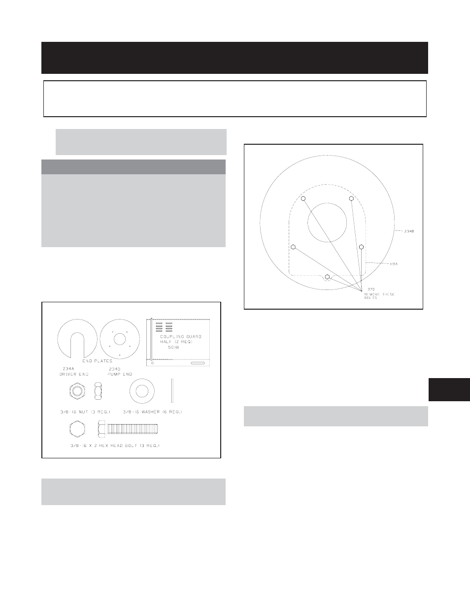
3.
Remove five thrust bearing end cover/bearing frame
screws (370N) as indicated in Fig. I-B.
4.
Align the end plate (234B) to the thrust bearing end
cover (109A) so that the five holes in the end plate
align with the bolt holes in the end cover.
5.
Replace the three to five thrust bearing end
cover/bearing end cover bolts (371S) and torque to
values provided in Table 11 (p. 72).
6.
Replace coupling hub (if removed) and reconnect the
coupling. Refer to coupling manufacturer’s
instructions for assistance.
NOTE: Coupling adjustments should be completed
before proceeding with coupling guard assembly.
3420 IOM 8/09
99
Fig I-A
Fig I-B
8