Install the impeller – Goulds Pumps 3198 i-FRAME - IOM User Manual
Page 97
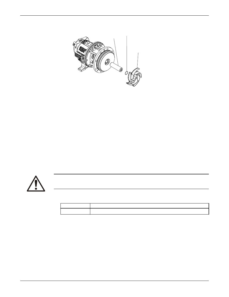
412A
101
126
2. Mark the shaft and sleeve at the face of the seal chamber.
3. Continue the complete reassembly of the pump, except for the mechanical seal.
4. Set the impeller clearance.
Refer to the Impeller clearance setting section for more information.
5. Scribe a line on the marked shaft and sleeve at the face of the seal chamber.
6. Remove the casing, the impeller, and the seal chamber.
7. Install the mechanical-seal rotary unit per the manufacturer's instructions.
Use the scribed line as the seal-reference dimension. Be sure to secure the rotary unit in place using
the set screws in the locking ring.
8. Install the gland, with the stationary seat and gland gaskets installed, on the seal chamber.
9. Reinstall the seal chamber.
10. Complete the reassembly of the pump.
Install the impeller
CAUTION:
Wear heavy work gloves when you handle impellers. The sharp edges can cause physical injury.
1. Install the impeller.
Pump size
Action
STi, MTi
Install the impeller (101) with an O-ring (412A).
2. Attach a shaft wrench and a coupling key on the shaft.
a) When the impeller (101) makes firm contact with the sleeve (126), raise the shaft wrench
(counterclockwise, viewed from the impeller end of the shaft) off of the bench and slam it down
(clockwise, viewed from the impeller end of shaft).
b) Apply a few sharp raps to tighten the impeller (101).
Maintenance
Model 3198 i-FRAME Installation, Operation, and Maintenance Manual
95