Appendix vii-1, Warning – Goulds Pumps ANSI FAMILY IOM (ATEX Compliant) - IOM User Manual
Page 139
APPENDIX VII-1
Double Row Angular Contact Bearing Installation Instructions
1.
Inspect the shaft (122) to ensure that it is clean,
dimensionally correct, and is free of nicks, burrs,
etc.
2.
Lightly coat the bearing seating with a thin film of
oil.
3.
Remove the bearing (112) from its packaging.
4.
Wipe the preservative from the bearing (112) bore
and outer diameter.
5.
Use an induction heater with a demagnetizing
cycle to heat bearing (112) to an inner ring
temperature of 230 °F (110 °C).
s
!
WARNING
Wear insulated gloves when using a bearing
heater. Bearings will get hot and can cause
physical injury.
6.
Position the bearing (112) on the shaft (122)
against the shoulder and snug the locknut (136)
against the bearing until it is cool. The locknut
prevents the bearing from moving away from the
shaft shoulder as it cools.
NOTE: Regreasable bearing has a single shield.
The outboard bearing is installed with shield
toward impeller.
7.
Remove bearing locknut (136) after bearing (112)
has cooled.
8.
Place lockwasher (382) on shaft (122). Place
tang of lockwasher in keyway of shaft.
9.
Thread locknut (136) onto shaft (122). Tighten
locknut one-eighth (1/8) to one-quarter (1/4) turn
beyond snug. Bend any tang of lockwasher (382)
into a slot of locknut.
NOTE: Tighten locknut if necessary to align the
closest tab of lockwasher with slot on locknut,
but do not overtighten. See Table VII-1 for
maximum locknut torque.
ANSIFAM IOM - 5/08
137
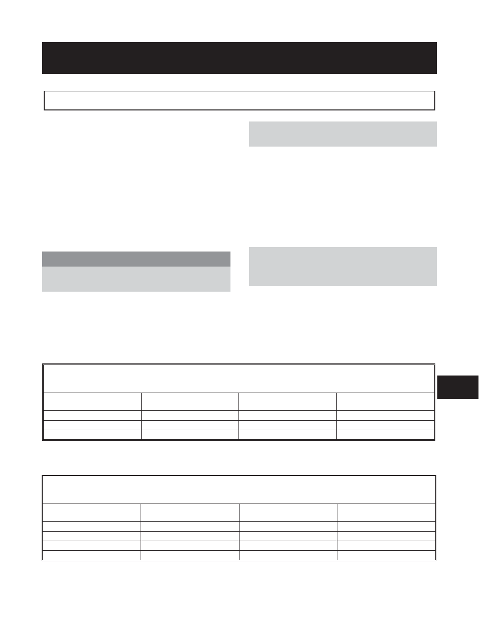
Table VII-2
Maximum Bearing Locknut Torque
Group
Bearing Size
Locknut Size
Maximum Torque
Ft-Lb (N
!m)
STX
7306
N-06
20 (27)
MTX
7309
N-09
50 (68)
LTX
7310
N-10
70 (95)
XLT-X, X17
7313
N-13
140 (190)
Table VII-1
Maximum Bearing Locknut Torque
Group
Bearing Size
Locknut Size
Torque
Ft-Lb (Nm)
STX
5306
N-06
20 (27)
MTX
5309
N-09
50 (68)
XLT-X, X17
5313
N-13
140 (190)
8