Ctcii main circuit board figure v.a.1, Ctcii – Myron L CTCIITD User Manual
Page 24
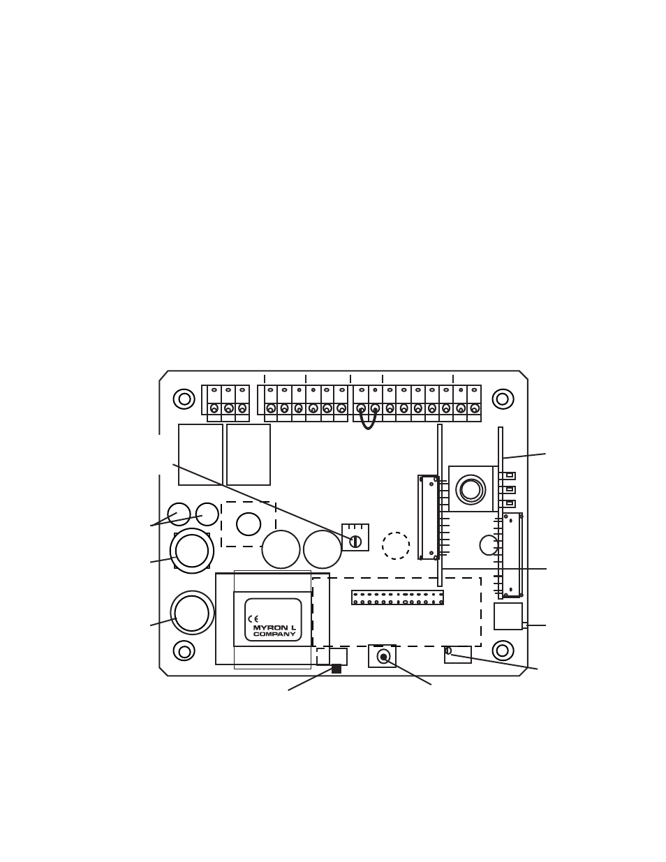
V. COMPONENT IDENTIFICATION,
CALIBRATION AND PREVENTIVE CARE
A.
PRIMARY COMPONENT IDENTIFICATION
As identified in Section III, the CTCII Chemical Treatment
Controllers main circuit board, controls and indicator lights are
mounted directly to the front panel.
Review figure V.A.1 below to familiarize yourself with the Main
circuit board assembly. The following diagram has the optional
Limit Timer Module and 4-20 mA Output Module installed.
CTCII MAIN CIRCUIT BOARD
Figure V.A.1
115/230 VAC
SELECT SWITCH
100mA Slow Blow
(T.10A)
115 & 230 VAC (V~)
SCALE SELECT
ELECTRONIC
CALIBRATION
MAIN
CALIBRATION
CONTROL
DISPLAY
CALIBRATION
CONTROL
(FACTORY SET)
OPTIONAL
LIMIT
TIMER
CONTROL
MODULE
OPTIONAL
4-20 mA
OUTPUT
MODULE
DIS
CAL
TDS
COND
EC
CTCII
DISPLAY
TRANSFORMER
Yel
CAP
CAP
C4AM
LTM
HYST
Flow Switch
Jumper -
Remove if
flow switch
installed.
SWITCH
FUSE
RELAY
RELAY
BLEED FEED
FEED
PUMP
BLEED
VALVE
POWER
FLOW
SWITCH
SENSOR
0-10VDC
FS BK WTRD GN NU R- R+
PWR
C GD
PWR
C GD
PWR
C GD
SET POINT
HYSTERESIS
RIGHT INC
LEFT DEC
R/G
Wickman Fuse 5 Amp
(#3741500041 or equiv)
115 VAC(V~)
20