Myron L CTCIITD User Manual
Page 17
E. 0-10 VDC RECORDER OUTPUT
The 0-10 VDC output is designed to give the user the capability
of sending a signal to a remote meter, recorder, PLC or SCADA
system.
Requirements
A hole of the proper size must be drilled in the enclosure. The
user/installer must choose a location that will NOT interfere with
normal operation. To ensure waterproof integrity, a watertight
cable restraint must be used. Failure to do so or improper
installation will void the warranty and may be costly to repair.
1. CONNECTION
1. Drill appropriate size hole.
2. Place the user supplied interface cable and watertight
cable restraint into the hole.
3. Connect the Recorder’s plus (+) and minus (-) terminal
wires to the Recorder output connectors. (See figure
II.E.2.)
4. Refer to Section V.B.1.b for the procedures to calibrate
the 0-10 VDC voltage output.
2. VOLTAGE DIVIDER
A voltage divider gives the user the ability to scale or tailor the
output to a particular need or requirement due to the input of
another device, i.e. the output of the Main CB is 0-10V while the
input requirement of a particular recording device is 0-5V.
a. INSTALLATION
Briefly—
Two resistors are installed across the 0-10V output.
The output is recalibrated to required voltage.
Requirements
Select two (2) resistors as listed;
For 0-5V Output both “A & B” are 2K Resistors.
For 0-1V Output “A” is a 9K resistor and “B” is a 1K resistor.
WARNING: BEFORE STARTING, IF MONITOR/CONTROLLER
IS INSTALLED, ENSURE THE POWER IS OFF. FAILURE TO
DO SO COULD CAUSE DAMAGE TO THE INSTRUMENT, AND
COULD BE HARMFUL OR FATAL TO PERSONNEL. ONLY
QUALIFIED PERSONNEL SHOULD INSTALL ELECTRICAL
EQUIPMENT.
Physical
If the front panel has all ready been removed from the enclosure
skip to #3.
1. Using a Phillips Head screwdriver remove the four (4)
screws on the clear cover.
2. Remove clear cover.
3. The front panel is held in place with hook & loop strips
on each side. By carefully lifting at the slot on the top,
the front panel will pull toward you. Do not pull more than
about 8 inches/20CM.
DO NOT pull on control knob(s).
4. Rotate the front panel down so that the back side is
facing you. The Circuit Board is mounted to the back of
the front panel.
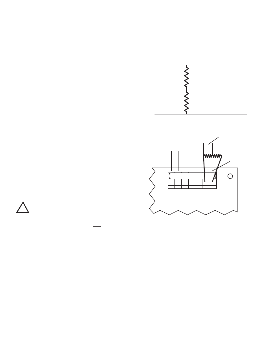
5. Solder two selected resistors together as shown in figure
II.F.1.
6. Attach leads to recording device as shown in figure II.F.1.
7. Attach resistors to 0-10V Output as shown in figure II.F.2.
Ensure resistors and leads DO NOT short to each other
or to any part of the CB assembly.
8. Recalibration is required, see Calibration Procedures,
section V.B.
Reassembly
1. Carefully reinstall the front panel, ensure no wires have
been pinched.
2. Reinstall the clear cover.
3. Reinstall the four (4) screws and tighten.
4. If desired, install corner covers.
5. To operate, turn power ON.
Figure II.F.1
0-10V Output
+
-
A
B
+
-
Recording
Device
Figure II.F.2
BK WT RD GN NU R- R+
SENSOR LEADS
Main CB Assembly
0-10VDC
OUTPUT
- +
NEW
OUTPUT
AS
SELECTED
!
CAUTION
- READ FOLLOWING CAREFULLY
13