Self - powered, Remote - powered – Myron L CTCIITD User Manual
Page 20
Specifications
Self-Powered and Remote-Powered
Drive Impedance — 0 to 600Ω
Common Mode Maximum — 120 VAC @ 60 Hz
Isolation — 100pf max. to Model 750II circuit common
100pf max. to input power line
Calibration
Two multi-turn pots — Factory Set.
4mA
=
Zero (0)
20mA
=
12 mA - Mid Scale
Calibration is NOT required. However, if you feel you must verify
or recalibrate, see RECALIBRATION.
2. INSTALLATION
Briefly -
The C4A Module simply plugs into the CTCII circuit board, see
Figure III.B.4. Connect signal wires per figure III.B.1 or III.B.2.
WARNING: BEFORE STARTING, IF MONITOR/CONTROLLER
IS INSTALLED, ENSURE THE POWER IS OFF. FAILURE TO
DO SO COULD CAUSE DAMAGE TO THE INSTRUMENT, AND
COULD BE HARMFUL OR FATAL TO PERSONNEL. ONLY
QUALIFIED PERSONNEL SHOULD INSTALL OR SERVICE
ELECTRICAL EQUIPMENT.
Physical
1. Using a Phillips Head screwdriver remove the four (4)
screws on the clear cover.
2. Remove clear cover.
3. The front panel is held in place with hook & loop strips
on each side. By carefully lifting at the slot on the top,
the front panel will pull toward you. Do not pull more than
about 8 inches/20CM.
DO NOT pull on control knob(s).
4. Rotate the front panel down so that the back side is
facing you. The Circuit Board is mounted to the back of
the front panel.
5. Locate the connector on the Circuit Board labeled C4AM.
6. Align as shown.
7. Press into place. The module will click when fully seated.
Electrical
1. Connect the signal and power wires as required, as
shown in figures III.B.1. & III.B.2. This assumes you have
already connected the other end of the wires as required.
a. Place the remote interface cable and user supplied
watertight cable restraint into the enclosure’s
appropriate access hole.
b. Neatly connect the signal cable wires to the CTC’s
appropriate connectors as shown in figure III.B.3.
2. To test, turn power ON.
3. Press the EC switch and monitor the output at your
remote site, or with a DVM set to DC milliamps. Attach
the DVM to the output connectors per your requirements,
i.e. self-powered or remote-powered, see figures III.B.1.
& III.B. 2. If the C4A module is connected properly it will
indicate 12mA.
4. Turn power OFF.
5. Carefully reinstall the front panel.
6. Reinstall the clear cover
7. Reinstall the four (4) screws and tighten.
8. To operate, turn power ON.
!
CAUTION
- READ FOLLOWING CAREFULLY
-
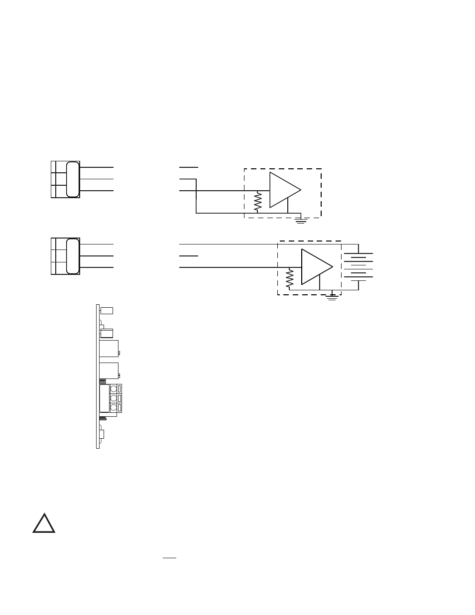
Figure III.B.1
(-)
CURRENT INPUT INSTRUMENT
Self - Powered
(+)
+
SIGNAL OUT
(+)
POWER OUT
POWER IN
+
NC
-
CURRENT INPUT INSTRUMENT
Figure III.B.2
Remote - Powered
(+)
(-)
+
NC
+ 35 VDC
MAXIMUM
(+)
+
SIGNAL OUT
POWER IN
POWER OUT
SO
PO
PI
SO
PO
PI
Figure III.B.3
PO
SO
PI
PO
T1
D
1
PO
T2
U4
R3
16