Warning ! 11, Figure ii.e.1 – Myron L CTCIITD User Manual
Page 15
C.
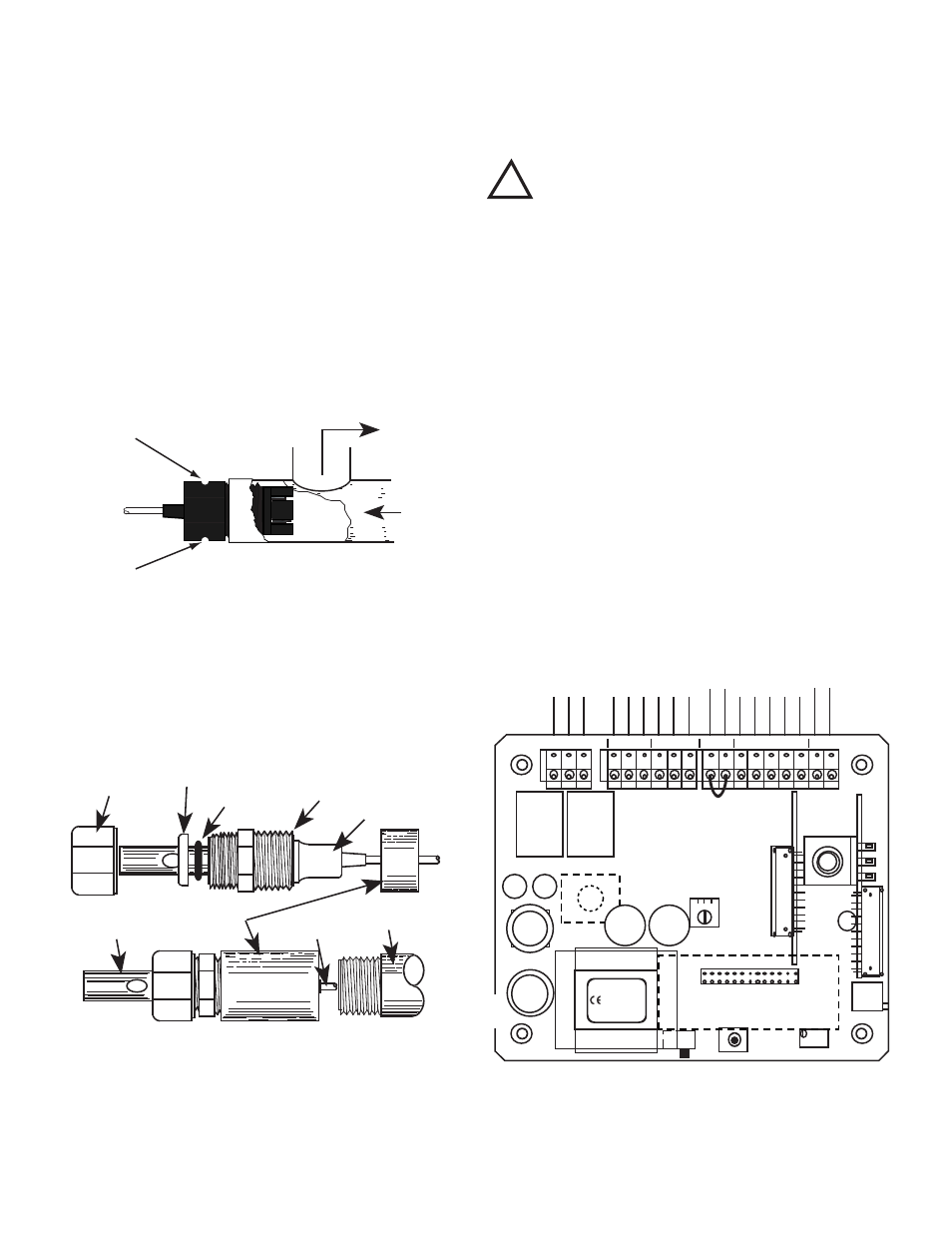
SENSOR INSERTION/IMMERSION MOUNTING
The Sensor’s mounting orientation must provide a continuous and
adequate circulation flow to prevent the trapping of air bubbles
within the Sensor’s electrode area (CSAR shown in figure II.D.1).
Failure to do so will result in conditions that may prevent the
Sensor from functioning properly. The CSAR sensor is designed
for insertion (in-line installation). The optional CS51R sensor may
be ordered and installed as either insertion, or immersion (see
figure II.D.2).
1. INSERTION MODE (in-line installation)
Use approved sealant, i.e. Teflon tape as required.
1. Pre-wind CSAR sensor before installation. Rotate sensor
counter clockwise (CCW) (as if removing sensor) 4-5
turns before installing into fitting.
2. Insert the Sensor Fitting assembly into the “T” fitting with
electrode aligned with direction of flow as shown in figure
II.D.1. and tightly secure. Note: The CS51R installs in
the same manner. (but does not require any turns)
2. IMMERSION OR DIP SENSOR ASSEMBLY
Use approved sealant, i.e. Teflon tape as required.
1. Verify that the CS51R Sensor’s Fitting assembly is
properly assembled as shown in figure II.D.2.
2. Insert and pull the Sensor’s cable through the extension
tube and then tightly attach extension tube to Sensor
assembly as shown in figure II.D.2.
D.
ELECTRICAL INSTALLATION
As shipped from the factory, the input power cable, the two
(2) output connectors, and the sensor are pre-wired to the
controller. Electrical connection simply requires plugging in
the appropriate valve and pump, and input power as labeled.
A device to disconnect the Model CTCII from the power
supply is required. It is recommended that this switch or
circuit breaker be labeled as the disconnection device for the
Model CTCII.
WARNING: All CTCII controllers are factory set for 115 VAC.
Before starting, ensure the input power “115/230” selection
is correct for your requirements. Failure to do so is beyond
the responsibility of the Myron L Company. See section II.D.1.
below and figure II.E.1.
NOTE: Some models, if ordered, have either a 24 VAC or a 24
VDC input power requirement - check labels carefully.
The following instructions are if the input power, output power or
sensor cables are removed.
The electrical installation procedures provided in this manual are
common to all CTCII controllers. Unless otherwise instructed,
refer to figure II.E.1. for the CTCII controller’s terminal block
connector wiring designations.
CSAR INSERTION MODE
Figure II.D.1
OUT
IN
DOT
DOT
CABLE
SENSOR TIP
COUPLING
3/4" NPT
EXTENSION TUBE
SECURING NUT
PLASTIC
WASHER
O-RING
THREADED FITTING
3/4" FNPT
FLANGE
IMMERSION OR DIP CS51R SENSOR
ASSEMBLY SHOWN
Figure II.D.2
FUSE
ELECTRICAL CONNECT DIAGRAM
Figure II.E.1
DIS
TRANSFORMER
DISPLAY
Yel
FEED
PUMP
BLEED
VALVE
POWER
FLOW
SWITCH
SENSOR
0-10VDC
C4AM
LTM
HYST
CAL
PWR
C GD
PWR
C GD
PWR
C GD
FS
BK WT RD GN NU R- R+
Flow Switch
Jumper -
Remove if
flow switch
installed.
TDS
COND
MYRON L
COMPANY
CTCII
BL
K
W
H
T
R
ED
G
R
N
N
EU R- R+
PO
W
ER
C
O
M
M
G
R
O
U
N
D
PO
W
ER
C
O
M
M
G
R
O
U
N
D
PO
W
ER
C
O
M
M
G
R
O
U
N
D
INPUT POWER
SENSOR
FEED
PUMP
BLEED
VALVE
FLOW
SWITCH
0-10 VDC
EC
SWITCH
BLEED FEED
CAP
CAP
RELAY
RELAY
115/230 VAC
SELECT SWITCH
!
WARNING !
11