Remote - powered nc self - powered – Myron L CTCIITD User Manual
Page 21
3. RECALIBRATION
The 4-20 Module was calibrated at the factory, however, if you
wish to check the calibration the following procedure will help you
to accomplish this task. Exercise caution while performing this
procedure.
Requirements; a DVM set to DC milliamps, a tweaker or small
standard slot screwdriver.
This procedure assumes the front panel is removed.
1. If sensor is connected, disconnect sensor wires from
sensor terminal block.
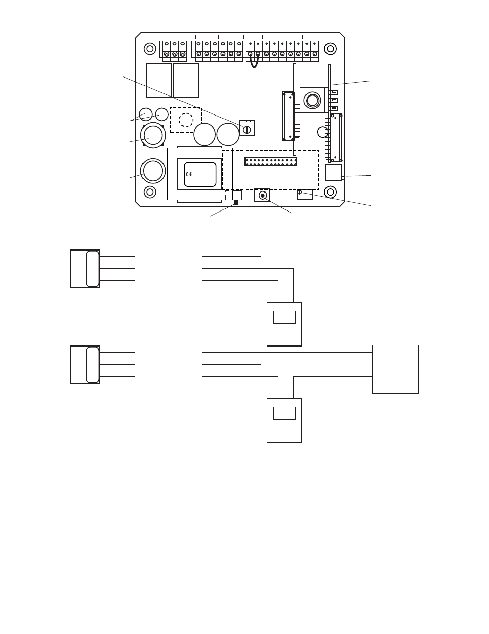
2. Attach the DVM to the output connectors per your
requirements, i.e. self-powered or remote-powered, see
figure III.B.5.
3. Turn power ON, with the display (if included) at ZERO or
ZERO DC volts out at Recorder, the DVM should indicate
4 mA at the signal out.
4. If not, adjust the CAL control marked “4mA” until the
DVM indicates 4 mA, see figure III.B.3.
5. Press the EC switch, the DVM should indicate 12 mA.
6. If not, adjust the CAL control marked “20mA” until the
DVM indicates 12 mA. See figure III.B.3.
NOTE: The C4A is linear, calibration at mid scale will not effect the
accuracy.
7. Calibration is complete.
8. Turn power OFF.
9. Reinstall the clear cover
10. Reinstall the four (4) screws and tighten.
11. To operate, turn power ON.
-
+
POWER IN
NC
+
Remote
Power
Supply
(+)
(-)
(+)
SIGNAL OUT
POWER OUT
POWER IN
+
-
(+)
(-)
(+)
SIGNAL OUT
POWER OUT
Figure III.B.5.
Remote - Powered
NC
Self - Powered
+
-
+
SO
PO
PI
SO
PO
PI
DVM
DVM
MYRON L
COMPANY
Flow Switch
Jumper -
Remove if
flow switch
installed.
C4AM
LTM
ELECTRONIC
CALIBRATION
DIS
Figure III.B.4.
SCALE SELECT
SET POINT
HYSTERESIS
RIGHT INC
LEFT DEC
115/230 VAC
SELECT SWITCH
100mA Slow Blow (T.10A)
115 & 230 VAC (V~)
SWITCH
FUSE
RELAY
RELAY
CAP
CAP
HYST
BLEED
BLEED
VALVE
POWER
FEED
PUMP
FLOW
SWITCH
SENSOR
0-10VDC
PWR
C GD
PWR
C GD
PWR
C GD
FS
BK WTRD GN NU R- R+
DISPLAY
Yel
CAL
MAIN
CALIBRATION
CONTROL
DISPLAY
CALIBRATION
CONTROL
(FACTORY SET)
OPTIONAL
LIMIT
TIMER
CONTROL
MODULE
OPTIONAL
4-20 mA
OUTPUT
MODULE
TDS
COND
CTCII
EC
FEED
TRANSFORMER
Wickman Fuse 5 Amp
(#3741500041 or equiv)
115 VAC(V~)
17