Myron L CTCIITD User Manual
Page 16
1. 115/230 VAC CONVERSION
1. Before turning power on to the CTCII controller ensure
the proper input voltage has been selected. Failure to
do so will blow the fuse. It could, under some conditions,
cause injury and damage the instrument voiding the
warranty.
2. Locate switch located next to the fuse holder.
3. Using a screwdriver, turn switch to required voltage.
2. CONNECTING THE SENSOR CABLE
If the sensor has been removed or requires replacement for any
reason.
1. Place the Sensor’s interface cable through the supplied
watertight cable restraint into the enclosure’s appropriate
access hole.
2. Install the sensor cable wire to comply with local
electrical codes*. Follow the color code as marked. See
figure II.E.1.
a. MODIFICATION FOR US PHARMACEUTICAL 25
(No Temperature Compensation)
This simple modification will allow your CTCII Chemical
Treatment Controller to meet USP 25 requirements by defeating
the normal temperature compensation circuit thus giving
“uncompensated” readings as required. Rarely will this be
required in the normal applications of this type of controller.
However, if it becomes necessary, the following will step you
through it.
Specifications:
As required to meet USP 25.
Installation
Briefly -
A resistor is installed in place of the sensor “temperature” sensing
leads.
The extra sensor leads are either cut off or the ends are wrapped
in tape to prevent shorting.
WARNING: BEFORE STARTING, IF CTCII CONTROLLER IS
INSTALLED, ENSURE THE POWER IS OFF. FAILURE TO DO
SO COULD CAUSE DAMAGE TO THE INSTRUMENT, AND
COULD BE HARMFUL OR FATAL TO PERSONNEL. ONLY
QUALIFIED PERSONNEL SHOULD INSTALL OR SERVICE
ELECTRICAL EQUIPMENT.
Requirements:
One 1.1kΩ .1% resistor, user supplied or may be ordered from the
Myron L Company.
NOTE: When opening instrument, remove front panel with care.
1. Using a Phillips Head screwdriver remove the four (4)
screws on the clear cover.
2. Remove clear cover.
3. The front panel is held in place with hook & loop strips
on each side. By carefully lifting at the slot on the top,
the front panel will pull toward you. Do not pull more than
about 8 inches/20CM.
DO NOT pull on control knob(s).
4. Rotate the front panel down so that the back side is
facing you. The Circuit Board is mounted to the back of
the front panel.
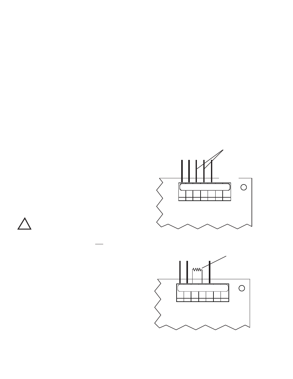
5. If sensor is installed, locate and remove the RED (RD)
and the GREEN (GN) leads from MAIN Circuit Board, as
shown in figure II.E.2.
6. Cut off or tape RED (RD) and the GREEN (GN) leads
from sensor.
7. Install 1.1kΩ resistor at RED (RD) and the GREEN (GN)
connector locations, as shown in figure II.E.3.
8. Carefully reinstall the front panel.
9. Reinstall the clear cover
10. Reinstall the four (4) screws and tighten.
11. To operate, turn power ON.
NOTE: Recalibration will require both the solution and sensor be
at 25°C for maximum accuracy.
3. FLOW SWITCH
A flow switch may be installed (electrically connected) utilizing the
FS connection*, see figure II.E.1, remove jumper and connect flow
switch leads to terminals.
*CAUTION: The connectors require only a small screwdriver or
a pen to push on the release levers. The release levers may be
broken or damaged if not pushed straight toward the circuit board.
DO NOT push the release levers sideways.
INSTALL 1.1K�
RESISTOR HERE
BK WT RD GN NU R- R+
SENSOR LEADS
Main CB Assembly
Figure II.E.3
Main CB Assembly
Figure II.E.2
SENSOR LEADS
REMOVE THESE TWO LEADS
BK WT RD GN NU R- R+
0-10VDC
OUTPUT
!
CAUTION
- READ FOLLOWING CAREFULLY
12