Iv. operating procedures – Myron L CTCIITD User Manual
Page 22
IV. OPERATING PROCEDURES
A.
FRONT PANEL INDICATORS & CONTROLS
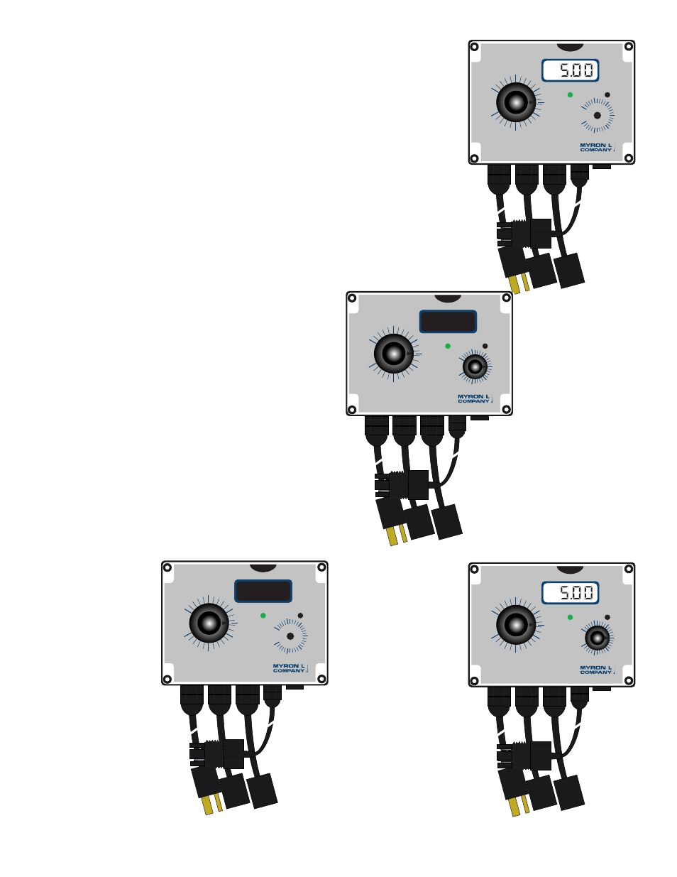
The front panel illustrations to the right and operational
descriptions have been provided to assist the user in identifying
and operating their CTCII controller.
Refer to Section IV.B for Setup procedures and Section IV.B.1 for
Check-Out procedures.
1. GREEN LED INDICATOR
When the GREEN LED indicator light is ON the conductivity/TDS
reading is LOW or BELOW the set point. Controller relays are
OFF.
2. RED LED INDICATOR
When the RED LED indicator light is ON the conductivity/TDS
reading is HIGH or ABOVE the set point AND the controller relays
are ON.
3. SET POINT CONTROL
When the “SET POINT” control is rotated the LED indicator light
will change from GREEN to RED and back as the knob is rotated.
The relay will switch ON and OFF. See figures IV.A.1 thru 4.
4. DIGITAL DISPLAY MODELS
Digital display provide a continuous readout of the water being
controlled.
Models CTCIID & CTCIITD are equipped with a 3 1/2 digit, 1/2”
Liquid Crystal Digital Display, as shown in figures IV.A.2 & 4, with
a 4 1/2 digit backlit LCD as an option.
5. LIMIT TIMER MODELS
Models CTCIIT & CTCIITD incorporate a Limit Timer for the feed
pump. The time may be set up to 120 minutes after which the
pump will turn off even though the controller may still be bleeding.
While the feed pump Limit Timer is ON a YELLOW LED will turn
ON. When the Limit Timer times out the YELLOW LED will turn
OFF.
60
80
100
120
0
1000
2000
3000
4000
5000
40
20
0
MICROSIEMENS / CM
CTCII
EC
MINUTES
60
80
100
120
0
1000
2000
3000
4000
5000
40
20
0
MICROSIEMENS / CM
CTCII
EC
MINUTES
60
80
100
120
0
1000
2000
3000
4000
5000
40
20
0
MICROSIEMENS / CM
CTCII
EC
MINUTES
60
80
100
120
0
1000
2000
3000
4000
5000
40
20
0
MICROSIEMENS / CM
CTCII
EC
MINUTES
Controller with
LCD Display
CTCIID
Figure IV.A.2
Controller
with Timer
CTCIIT
Basic
Controller
CTCII
Figure IV.A.1
Controller
with LCD
Display and
Timer
CTCIITD
Figure IV.A.4
Figure IV.A.3
18