Ii. installation – Myron L CTCIITD User Manual
Page 14
II. INSTALLATION
A.
GENERAL
This section provides the recommended procedures for properly
installing your CTC Series II Chemical Treatment Controller, and
sensors.
WARNING: THE MYRON L COMPANY RECOMMENDS THAT
ALL MOUNTING AND ELECTRICAL INSTALLATIONS BE
PERFORMED BY QUALIFIED PERSONNEL ONLY. FAILURE
TO DO SO COULD CAUSE DAMAGE TO INSTRUMENT, AND
COULD BE HARMFUL OR FATAL TO PERSONNEL.
B.
MECHANICAL INSTALLATION
All CTCII electronics are packaged inside a waterproof/weather-
proof enclosure.
The enclosure is designed for surface mounting.
There are four basic guidelines to consider when selecting a
mounting location:
1. Select a site that limits the CTCII exposure to excessive
moisture and corrosive fumes (water flowing or dripping
directly on the power cords may cause an unsafe
condition, and is NOT recommended).
2. For best results, position your CTCII controller and
sensor as close as possible to the point being controlled.
The CTCII controllers are not designed to operate with a
sensor cable length that exceeds 100’ (30 meters).
3. Mount your CTCII controller at eye level for viewing
convenience.
1. SURFACE MOUNTING
NOTE: Due to the many variables of installations mounting
screws are not supplied. It is recommended that suitable #6 (M4)
screws for the exact conditions be used, i.e. woodscrews, metal
or sheetmetal.
1. Select mounting site location.
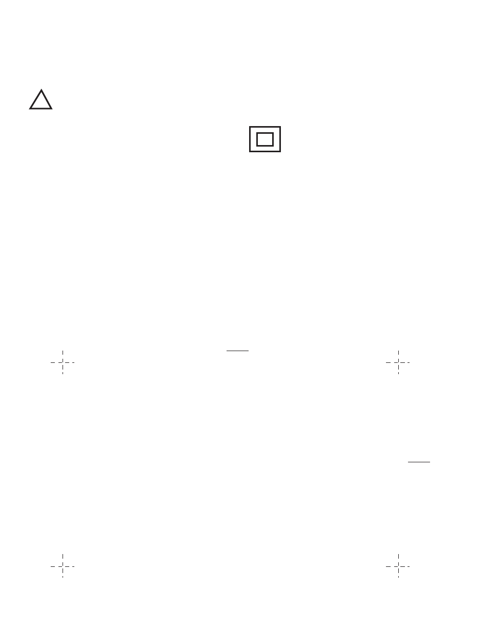
2. Mark and drill the required mounting holes. For hole
drilling locations, see figure II.B.1.
3. Hold the CTCII in place while starting and tightening the
mounting screws.
!
CAUTION
- READ FOLLOWING CAREFULLY
DOUBLE INSULATED
SURFACE MOUNTING DIAGRAMS
DIMENSIONS IN INCHES
(MILLIMETERS)
Figure II.B.1.
5.83"
(148mm)
3.54"
(90mm)
10