Myron L 760-A Aquaswitch User Manual
Page 9
2.3.4 PILOT VALVE SOLENOID CONNECTIONS
NOTE:
Section 2.3.4 provides the procedures for installing 115 VAC
solenoid valves with maximum load rates of 25 watts per valve.
For the procedures to install solenoid valves other than 115
VAC, see Section 2.3.4.1. (Refer to Fig. 2-10 for recommended
valve wiring.)
STEP 1 Place the Bank A solenoid interface cable and
watertight cable restraint into the enclosure’s
appropriate access hole.
STEP 2 Neatly connect the cable wires to Power Module
terminal block TB2 as shown in Fig. 2-5.
STEP 3 Repeat Steps 1 and 2 to install the Bank B solenoid
interface cable.
STEP 4 Repeat Steps 1 and 2 to install the Bleed Valve
solenoid interface cable.
STEP 5 (Optional) Repeat Steps 1 and 2 to install the Process
valve solenoid interface cable.
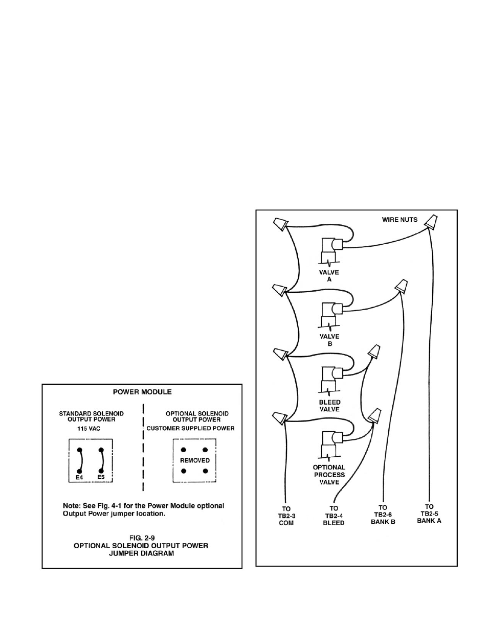
2.3.4.1 OPTIONAL SOLENOID POWER
CAUTION!
Prior to connecting any solenoid valves other than 115 VAC, it is
essential that the user remove Power Module jumpers E4 and
E5 as shown in Fig. 2-5 (detail in Fig. 2.9 below). Failure to do
so could result in damage to the equipment and/or property.
STEP 1 Place the optional solenoid power cable and watertight
cable restraint into the enclosure’s appropriate access
hole.
STEP 2 Connect the cable wires to the Power Module terminal
block TB2 as shown in Fig. 2-5.
2.3.5 CELL CONNECTIONS (MODEL 760-A ONLY)
STEP 1 Place the CS10 Cell’s interface cable and watertight
cable restraint into the enclosure’s appropriate access
hole.
STEP 2 Neatly connect the cable wires to the 760-A Control
board terminal block TB3 as shown in Fig. 2-6
2.3.6 ALARM RELAY INSTALLATION
STEP 1 Place the user supplied Alarm relay interface cable
and watertight cable restraint into the enclosure’s
appropriate access hole.
STEP 2 Neatly connect cable wires to the Power Module TB3
terminal connectors as shown in Fig. 2-5.
NOTE:
See Section 4.4 for the “ALARM RESET” jumper adjustments.
7