Myron L 760-A Aquaswitch User Manual
Page 13
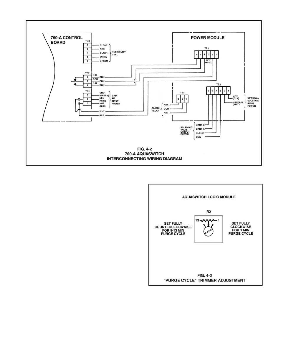
4.3 “PURGE CYCLE”. CALIBRATION PROCEDURES
NOTE:
The Purge Cycle trimmer adjustment screw (R2) (see Fig. 4-1)
determines the time span that the Bleed and Process solenoid
valves are energized during either a Bank A or B Purge Cycle.
STEP 1 Being careful not to excessively strain the cable(s),
unfasten the enclosure’s front panel.
STEP 2 Turn the Logic Module trimmer adjustment screw (R2) to
the desired Purge Cycle setting. (See Fig. 4-3)
NOTE:
Turning the adjustment screw fully clockwise equals a minimum
Purge Cycle of approximately one (1) minute. Turning the
adjustment screw fully counterclockwise equals a maximum Purge
Cycle of nine (9) to thirteen (13) minutes.
11
This manual is related to the following products: