Myron L 760-A Aquaswitch User Manual
Page 6
NOTE:
The 760-A Aquaswitch is not designed to operate with a Cell cable
length that exceeds 100' (30 meters).
3 If at all possible, mount the Controller at eye level for
viewing convenience.
2.2.1 SURFACE MOUNTING
NOTE:
Surface mounting will require two (2) user supplied 1/4” 20
mounting screws See, Fig. 2-1 for hole drilling locations. For ease
of surface mounting, a surface mounting plate is available.
Order Part No.: SMP50 for Aquaswitch
SMP60 for 760-A Aquaswitch
STEP 1 Select your site location. Mark and drill the two (2) required
mounting holes.
STEP 2 lace the mounting threads in alignment with the surface
mounting holes.
STEP 3 Insert and securely fasten the two (2)1/4':20 mounting
screws.
2.2.2 PANEL MOUNTING INSTALLATION
A panel mounting fastening kit is provided with all Aquaswitch/
760-A Aquaswitch enclosures. Panel mounting will require the use
of the fastening kit’s two (2) 4-40 mounting screws/nuts or two
(2) #4 x 1/2 “ sheet metal screws. See Fig. 2-1 for panel cutout
dimensions.
STEP 1 Select your site location, mark the appropriate pane I cut
out and complete the necessary panel cut.
STEP 2 Carefully unfasten and separate the front panel from its
enclosure.
STEP 3 Disconnect all panel cable(s)/wires from the enclosure’s
component board(s).
STEP 4 Slide the enclosure through the panel cutout until its flange
contacts the panel.
STEP 5 Insert mounting screws through the flange mounting holes
and tightly secure.
STEP 6 Reconnect all panel cable(s)/wires. (See Fig. 4-1)
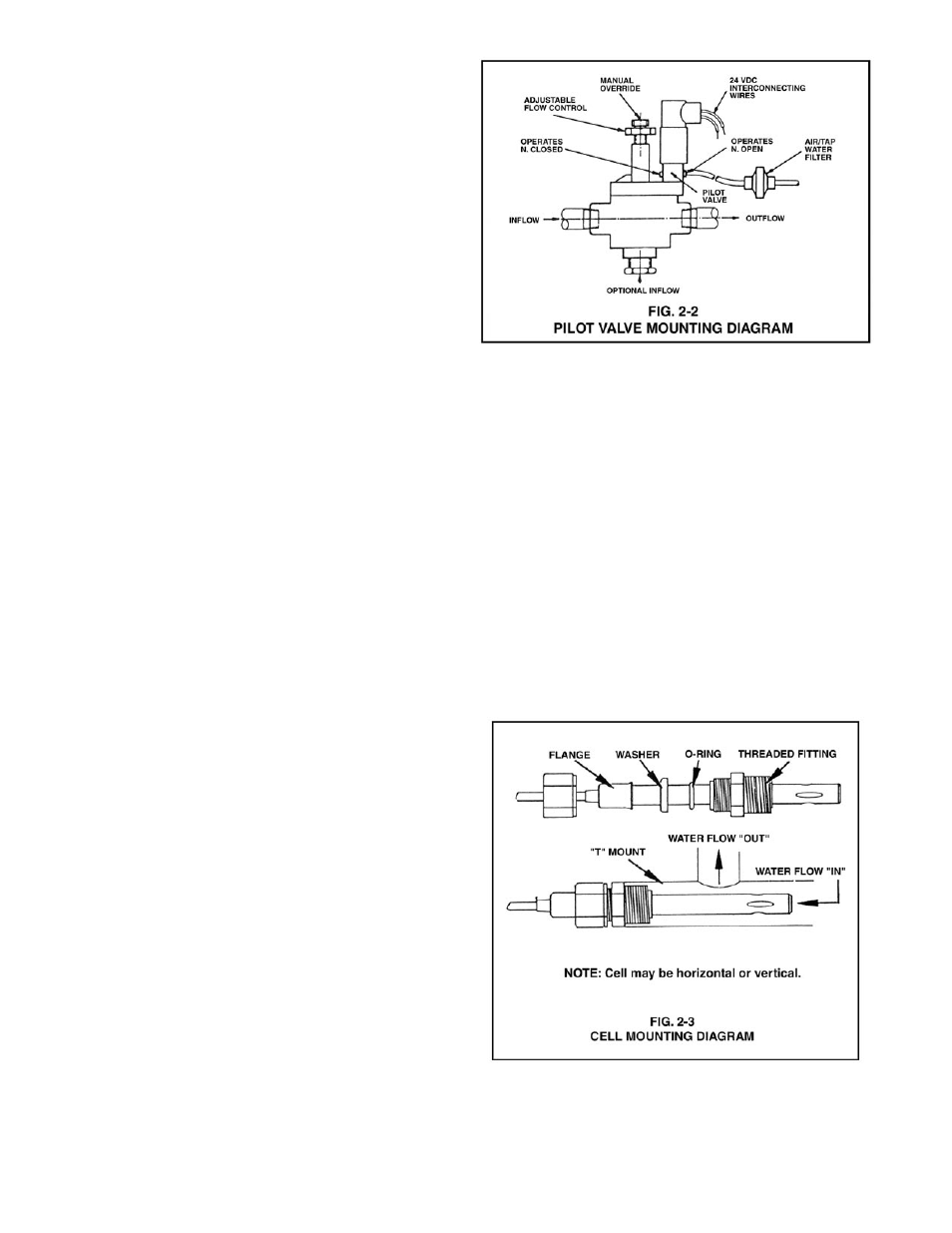
2.2.3 HP SOLENOID PILOT VALVE INSTALLATION
STEP 1 Insert the pilot valve unit so that the systems’ INFLOW
source and OUTFLOW process piping connecting ends
are inserted into the valve as shown in Fig. 2-2.
STEP 2 Repeat STEP 1 until all appropriate pilot valve units have
been installed.
NOTE:
The number of pilot valves used will be based upon the user’s
desired application.
2.2.4 CELL INSTALLATION (MODEL 760-A ONLY)
NOTE:
Fig. 2-3 illustrates how to properly assemble and install the CS10
Cell assembly into a “T” type mounting fixture. Improper assembly
could result in damage to equipment and/or property.
A CS10 Cell’s mounting orientation must provide a continuous
and adequate circulation flow to prevent the trapping of air bubbles
within the Cell’s electrode area. Failure to do so will result in
conditions that will prevent the cell from functioning properly.
STEP 1 Verify that the Cell components are properly
assembled.
STEP 2 Insert the Cell assembly into the “T” mounting fixture as
shown in Fig. 2-3 and tightly secure.
4