Important! please read – Myron L 760-A Aquaswitch User Manual
Page 17
IMPORTANT! PLEASE READ!
ADDENDUM TO USER’S MANUAL
AQUASWITCH 760A AQUASWITCH
Most Aquaswitch users choose Myron L HP
Series 24 vac valves. For this reason, we have
modified the circuit boards of the Aquaswitch
and 760 Aquaswitch, and made the necessary
corrections to the User’s Manual. As a result:
1. All power for solenoid valves, regardless
of voltage (24, 110, 220 vac, etc.) must be
connected separately to the Power Module
TB2, terminals 1 and 2. Line power to the
Aquaswitch is no longer used to power the
valves.
2. Disregard all Manual references to jumpers
E4 and E5. These are no longer installed
at the factory, and they will not be found on
the circuit board of your Aquaswitch or 760
Aquaswitch.
3. Your User’s Manual and the changes detailed
on this page should be closely followed.
SPECIFIC CHANGES TO USER’S MANUAL
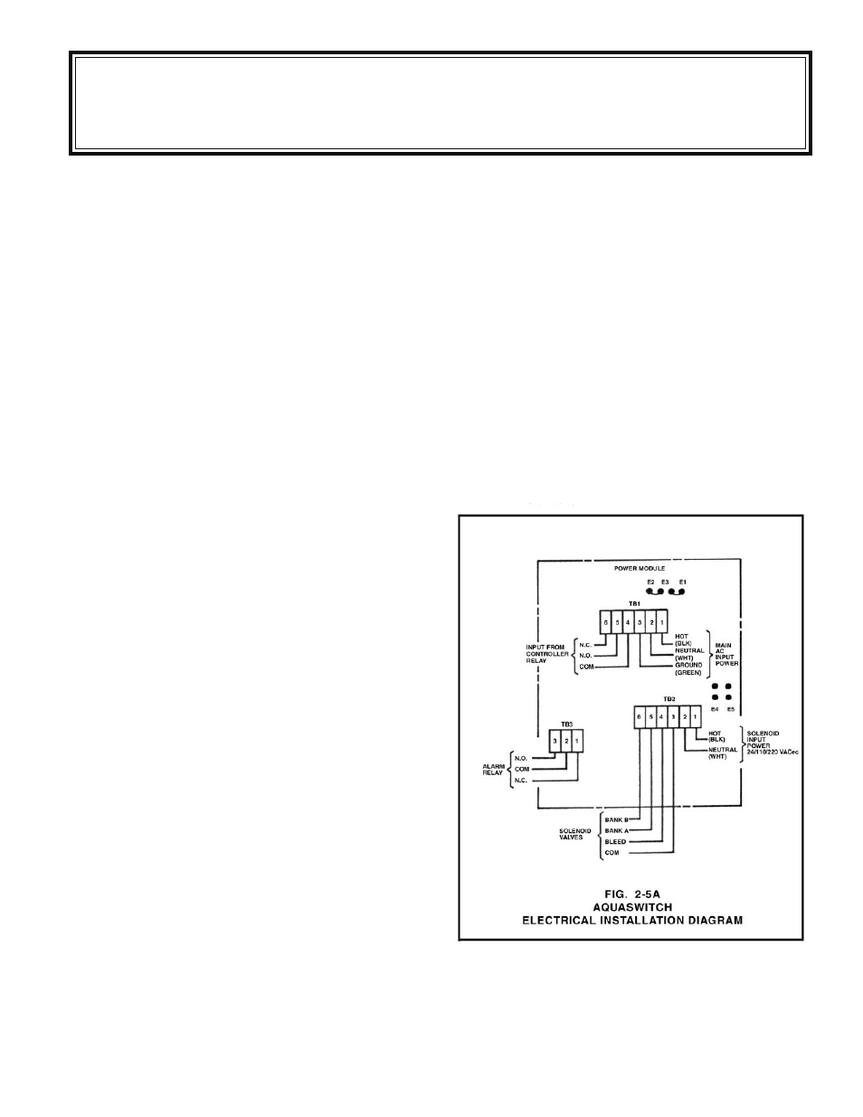
Page 5 of the User’s Manual, Figure 2-5 shows
jumpers E4 and E5 installed. Please note, they are
NOT installed. Figure 2-5 also shows “Optional
Solenoid Input Power” applied to TB2, Terminals
1 and 2. This is now the only method of powering
the valves.
See Fig. 2-5A at right, which replaces Fig.
2-5
Also on page 5, Section 2.3 mentions “optional”
Solenoid Power, depending on solenoid voltage.
All solenoid power, regardless of voltage, must
now be connected to Power Module TB2.
SPECIFIC CHANGES (cont’d)
Page 7, Figure 2-9 shows installed jumpers
E4 and E5 as standard. Also on Page 7, Section
2.3.4 assumes that jumpers have been installed.
These jumpers are no longer needed or provided.
Customer supplied power is the standard.
Page 10, Figure 4-1 shows jumpers E4 and E5
installed on the Power Module; they are no longer
needed or provided.
On Page 11, Figure 4-2 shows power supplied
to Power Module TB2, Terminals 1 and 2 as an
“option.” This is now the standard procedure
NOTE: This Addendum applies to all Aquaswitch models shipped from the factory after Oct. 4,
1987 (with the last 4 serial number digits greater than 7023).