Myron L 760-A Aquaswitch User Manual
Page 10
SECTION 3
Operating Procedures
3.1 GENERAL
Section 3.2 provides the operational descriptions for each of
the Aquaswitch/760-A Aquaswitch switch and indicator controls.
Section 3.3 provides the user with recommended checkout
procedures.
3.2 SWITCH AND INDICATOR CONTROLS
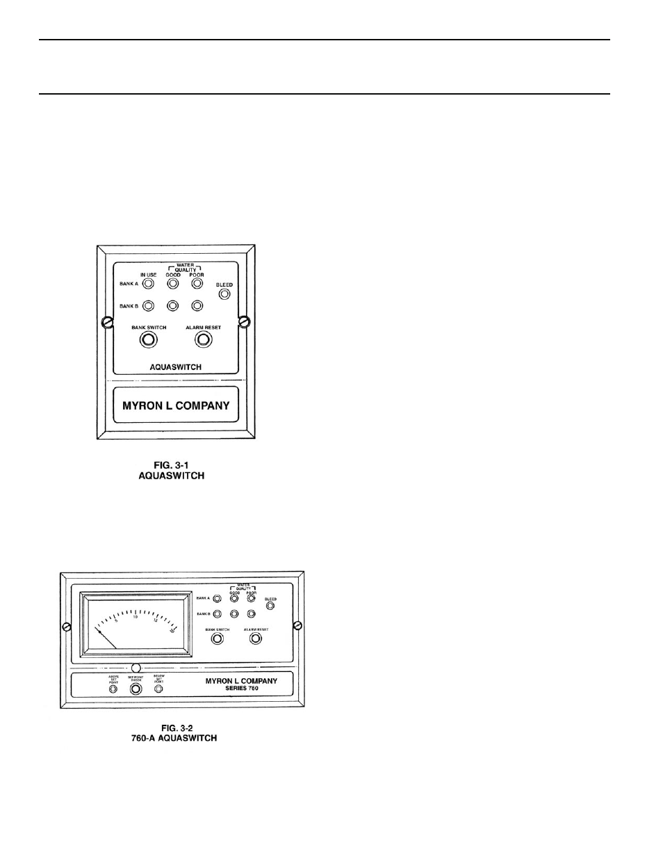
AQUASWITCH
BANK A/B “IN USE” Indicators
The amber “IN USE” LED indicator light is ON only when its
respective Bank’s solenoid valve is energized.
NOTE:
The units have been designed so that only one (1) Bank (either A
or B) can be in use at any time.
Water Quality “GOOD” Status Indicators
The green “GOOD” status LED light indicators are ON when
their respective Bank’s water quality is acceptable (ABOVE
Controller Set Point).
Water Quality “POOR” Status Indicators
The red “POOR” status LED light indicators are ON only when
their respective Bank’s water quality is unacceptable (BELOW
Controller Set Point).
“BLEED” Indicator Light
The amber “BLEED” LED indicator light is ON only when the
Aquaswitch is in its Purge Cycle (Bleed/Process Water valve(s)
are activated).
“BANK SWITCH” Push Button
When the “BANK SWITCH” is depressed, the Aquaswitch
automatically switches Banks, i.e. turns OFF the currently
selected Bank and turns ON the alternate Bank.
“ALARM RESET” Push Button.
When the-”ALARM RESET” switch is depressed, the Aquaswitch
will automatically turn OFF the Alarm.
760-A AQUASWITCH
4
1
/
2
" ANALOG METER
The 4
1
/
2
" (114mm) linear analog meter provides a continuous
readout of the water being monitored.
“ABOVE/BELOW” Set Point Indicators
The green LED indicator light is ON only when the resistance of
the water is ABOVE the Controller’s internal Set Point.
The red LED indicator light is ON only when the resistance of
the water is BELOW the Controller’s internal Set Point.
“SET POINT CHECK” Switch
When the “SET POINT CHECK” switch is depressed, the
internal Set Point reading is immediately displayed on the
analog meter.
8