Myron L 760-A Aquaswitch User Manual
Page 14
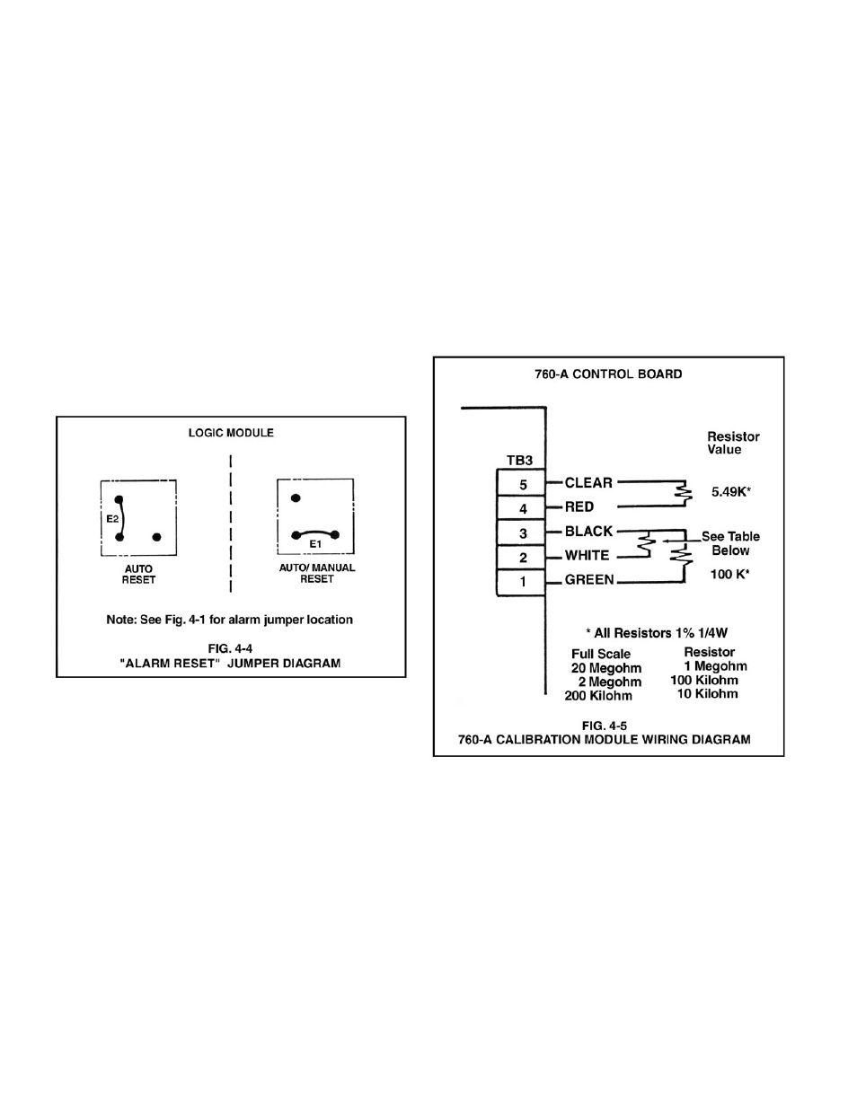
4.4 “ALARM RESET” JUMPER ADJUSTMENT
NOTE:
The Aquaswitch/760-A Aquaswitch are shipped with an Alarm
condition that occurs whenever the “IN USE” Banks are switched
automatically.
This section provides the user with the procedures for activating
an Alarm condition every time the “BANK SWITCH” is manually
pressed.
NOTE:
The Manual Bank Switch alarm condition is in addition to the
standard Automatic Bank Switch alarm condition.
To activate the Manual Bank Switch alarm condition, the user
must reinstall the Logic Module Alarm Reset jumper as shown in
Fig. 4-4.
STEP 1 Being careful not to excessively strain the cable(s),
unfasten the enclosure’s front panel.
STEP 2 Remove the Logic Module Jumper E2 and reinstall it into
its Jumper E1 position as shown in Fig. 4-4.
4.5 760-A AQUASWITCH CALIBRATION PROCEDURES
All 760-A Aquaswitches are calibrated and tested prior to
shipment.
4.5.1 METER MECHANICAL ZERO READING
STEP 1 Turn OFF the Aquaswitch main AC power and verify that
the meter is indicating a zero (0) reading. If the meter does
not indicate a zero (0) reading, proceed to STEP 2.
STEP 2 Remove the meter’s zero adjustment plug to access the
meter’s Mechanical Zero adjustment screw. (See Fig.
3-2)
STEP 3 Turn screw until meter indicates a zero (0) reading and
then replace the plug.
NOTE:
If it becomes necessary to replace a faulty meter, see Fig. 4-1 for
the meter wire/terminal designations.
4.5.2 INTERNAL SET POINT ADJUSTMENT
STEP 1 Being careful not to excessively strain the cable,
unfasten and remove the front panel.
STEP 2 While depressing the “SET POINT CHECK” switch, turn
the 760-A Control board’s R31 adjustment screw (see
Fig. 4-1) until the desired Set Point value is indicated
on the meter display.
NOTE:
The Controller’s Set Point setting is based upon the user’s
particular water purity specifications.
STEP 3 After successfully completing STEP 2, remount the
front panel and tightly secure both retaining screws.
12