Myron L 760-A Aquaswitch User Manual
Page 12
SECTION 4
Component Identification,
Calibration and Preventive Maintenance
4.1 GENERAL
Section 4.2 provides detailed illustrations to assist the user in
identifying the Aquaswitch/760-A Aquaswitch primary components
and cable connector designations.
Sections 4.3 and 4.4 provide the user with the Aquaswitch
Purge Cycle calibration procedures and Alarm Reset jumper
adjustment.
Section 4.5 provides the user with the 760-A Aquaswitch Calibration
procedures.
Section 4.6 provides the user with the Myron L Company’s
recommended Preventive Care procedures.
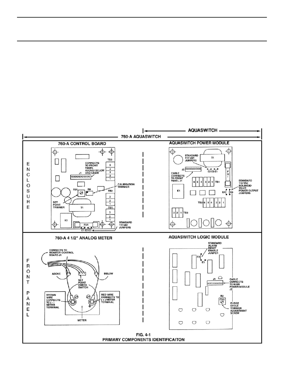
4.2 PRIMARY COMPONENT IDENTIFICATION
As identified in Section 3, the Aquaswitch/760-A Aquaswitch switch
and indicator components are mounted directly to the front panel.
Component boards and the 760-A Aquaswitch analog meter are
mounted within its enclosure or to the back of the front panel.
NOTE:
When performing Calibration procedures, the user must take
extreme care to contact only the trimmer adjustment screws located
on the Aquaswitch component boards. Failure to do so could result
in damage to equipment and/or property. (See Fig. 4-1)
10