Disassembly procedure flowchart – Acer 505 User Manual
Page 49
Chapter 3
43
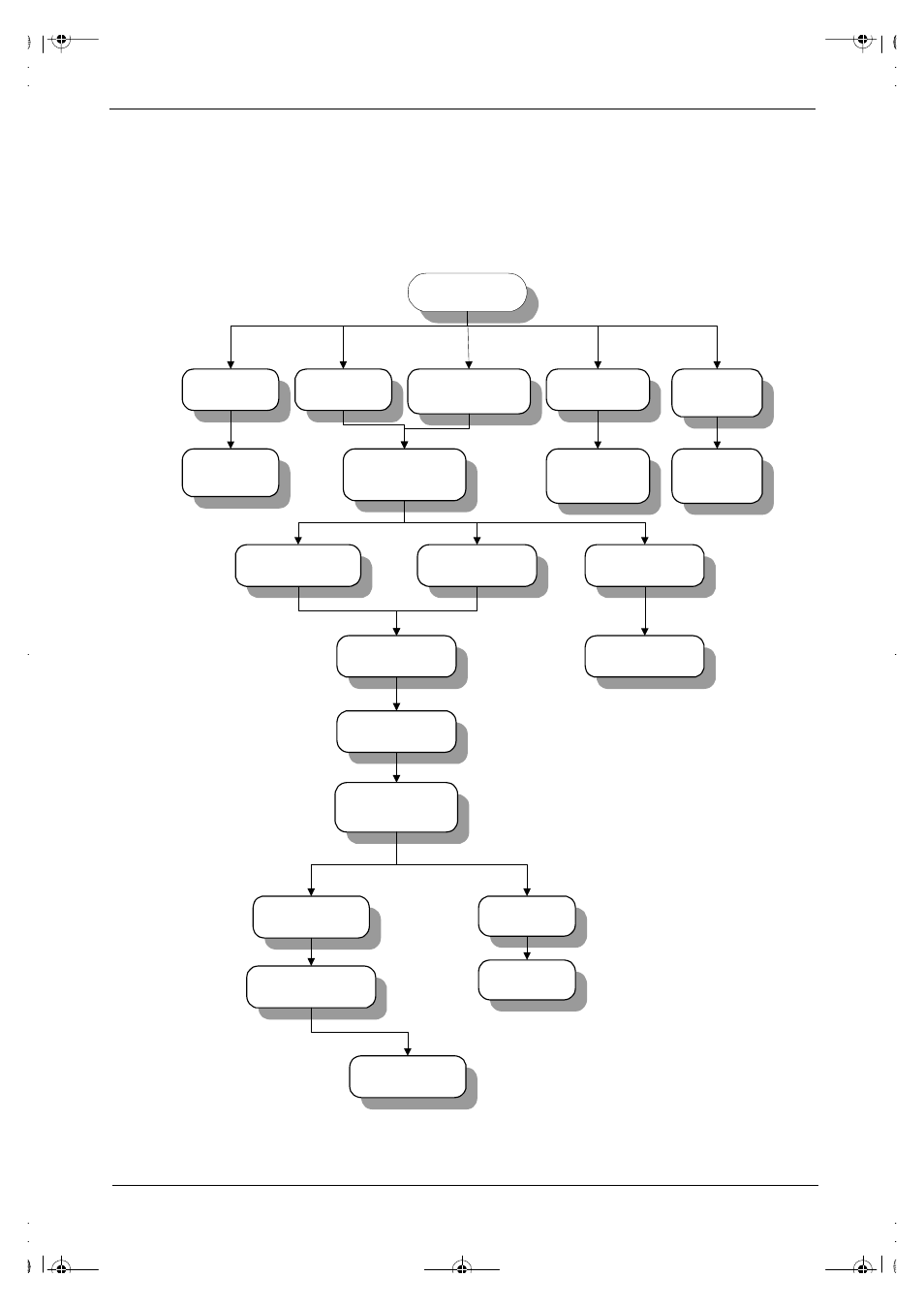
Disassembly Procedure Flowchart
The flowchart on the succeeding page gives you a graphic representation on the entire disassembly sequence
and instructs you on the components that need to be removed during servicing. For example, if you want to
remove the system board, you must first remove the keyboard, then disassemble the inside assembly frame in
that order.
S T A R T
Middle Cover
(short)
Hinge caps
M o d e m C o v e r
D I M M D o o r
Battery Pack
L E D B o a r d C a b l e
f r o m M / B
Battery Door
D I M M M o d u l e
M o d e m B o a r d
Middle Cover
( L o n g )
L E D B o a r d
LCD & Inverter
b o a r d
L C D F P C C a b l e
Inverter Board
8 6 . 1 A 5 2 2 . 1 4 0 * 2
S c r e w M A C H P A N
M 2 * 1 4 L
8 6 . 1 A 3 5 3 . 1 3 5
* 2 S c r e w
M A C H P A N
M 2 . 5 * 1 3 . 5 L
8 6 . 9 A 5 2 3 . 6 R 0 * 5 S c r e w
M 2 . 5 * 6 L B / Z N
8 6 . 9 A 5 2 2 . 4 R 0 * 2 S c r e w
M A C H P A N M 2 * 4 L
8 6 . 9 A 5 2 2 . 4 R 0 * 2 S c r e w
M A C H P A N M 2 * 4 L
8 6 . 5 A 5 2 4 . 4 R 0 * 4 S c r e w
M 3 * 4 L
K e y b o a r d
L C D F P C C a b l e
f r o m M / B
Main Unit
(see next page)
L C D M o d u l e
L C D B e z e l
L E D B o a r d
Cable
L C D P a n e l
505-1.book Page 43 Thursday, November 4, 1999 4:36 PM