Mechanical installation, General, Before installation – Beijer Electronics Industrial Inverter E2 User Manual
Page 9: Ul compliant installation, Guidelines for enclosure mounting – ip20 units
9
3. Mechanical Installation
3.1. General
The drive should be mounted in a vertical position only on a flat, flame resistant vibration free mounting using the integral holes or
DIN Rail clip (Frame Sizes 1 and 2 only). Do not mount flammable material close to the drive
The drive must be installed in a pollution degree 1 or 2 environment only.
Ensure that the minimum cooling air gaps are left clear
Ensure that the ambient temperature range does not exceed the permissible limits for the drive given in section 10.1
Provide suitable clean, moisture and contaminant free cooling air sufficient to fulfil the cooling requirements of the drive.
3.2. Before Installation
Carefully Unpack the BFI drive and check for any signs of damage. Notify the shipper immediately if any exist.
Check the drive rating label to ensure it is of the correct type and power requirements for the application.
To prevent accidental damage always store the drive in its original box until required. Storage should be clean and dry and within the
temperature range –40°C to +60°C
3.3. UL Compliant Installation
Refer to section 9.3 on page 27 for Additional Information for UL Compliance.
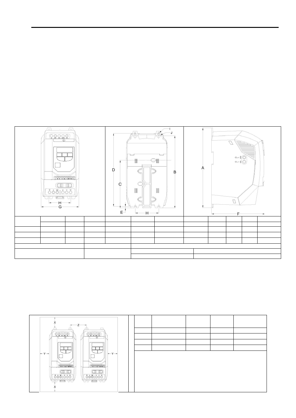
3.4. Mechanical Dimensions and Mounting – IP20 Open Units
Drive Size
A / Height
B
C
D
E
F / Depth
G / Width
H
I
J
Weight
mm
mm
mm
mm
mm
mm
mm
mm
mm
mm
kg
1
173
160
109
162
5
123
82
50
5.5
10
1,0
2
221
207
137
209
5.3
150
109
63
5.5
10
1,7
3
261
246
-
247
6
175
131
80
5.5
10
3,2
Mounting Bolts
All Frame Sizes
4 x M4
Tightening Torques
All Frame Sizes
Control Terminals
0.5 Nm
Power Terminals
1 Nm
3.5. Guidelines for Enclosure Mounting – IP20 Units
IP20 drives are suitable for use in pollution degree 1 environments, according to IEC-664-1. For pollution degree 2 or higher
environments, drives should be mounted in a suitable control cabinet with sufficient ingress protection to maintain a pollution
degree 1 environment around the drive.
Enclosures should be made from a thermally conductive material.
Where vented enclosures are used, there should be venting above the drive and below the drive to ensure good air circulation – see
the diagram below. Air should be drawn in below the drive and expelled above the drive.
The enclosure design and layout should ensure that the adequate ventilation paths and clearances are left to allow air to circulate through the
drive heatsink. The drive manufacturer the following minimum sizes for drives mounted in non-ventilated metallic enclosures:-
Drive
Size
X
Above & Below
Y
Either Side
Z
Between
Recommended
airflow
mm
mm
mm
CFM (m
3
/min)
1
50
50
33
0.31
2
75
50
46
0.31
3
100
50
52
0.74
Note:
Dimension Z assumes that the drives are mounted side-by-side with
no clearance.
Typical drive heat losses are 3% of operating load conditions.
Above are guidelines only and the operating ambient temperature of
the drive MUST be maintained at all times.